ACommunication
C
Ref. DCD01/3067 - UC500_en_D
19/27
Characteristics of the Inputs
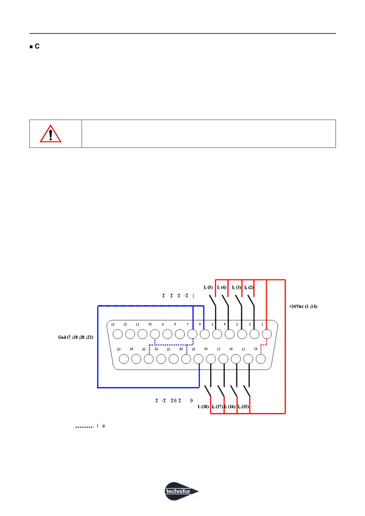
8 opto-insulated Inputs are available and controllable by positive logic.
They are divided into 2 groups. Each group has its own negative reference (pins 6 and 19), and must be wired to
the desired potential.
It is possible to control the Inputs with the + 24 V internal voltage available on pins 1 and 14, and referenced Gnd
on pins 7-10-20-23.
Note
The + 24 V internal voltage (pins 1 and 14) is not protected from short-circuits.
The current delivered by the + 24 V voltage (pins 1 and 14) should not exceed 300 mA.
• consumption and operating range of the Inputs
- applicable voltage per Input: 12 V - 24 V
- intensity consumed per Input: approximately 5 mA
• wiring of 8 inputs with power supplied by UC500
In this case the Inputs are no longer opto-insulated.
Negative reference
(common)
I
4-
I
5-
I
6-
I
7 (19)
Negative reference
(common)
I
0-
I
1-
I
2-
I
3 (6)
Internal connections
 Loading...