ACommunication
C
Ref. DCD01/3067 - UC500_en_D
13/27
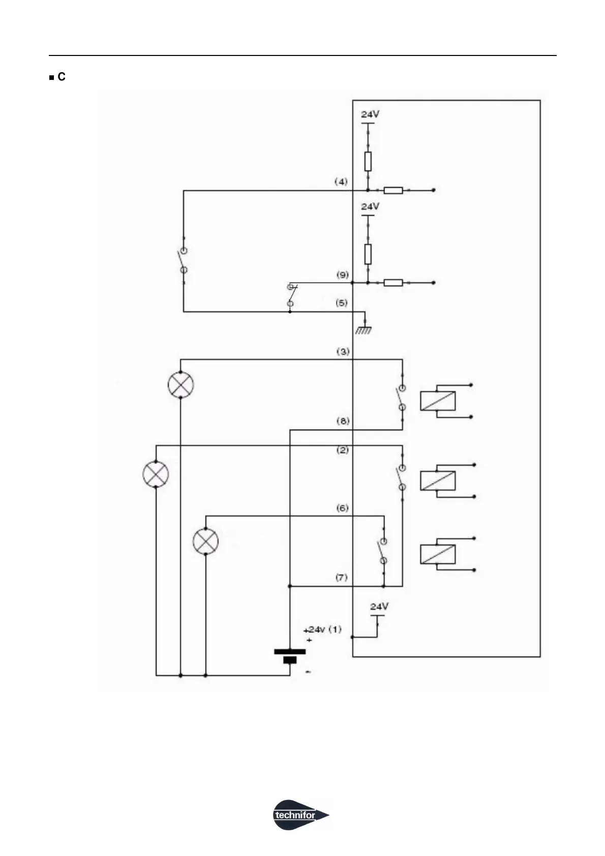
Connection diagram for the dedicated Inputs / Outputs
Note
In the diagram above, the Inputs are wired to the internal power supply, available on the connector of the CCU
(+ 24 V DC). The "Marking in progress", "Machine ready" and "Fault" Outputs are wired to an external power
supply.
SubD 9F Machine Communication
CCU side
Start marking
External contact
Stop marking
Gnd
Fault
Marking in progress
External light
Machine ready
Common Relay
Marking in progress
External light
External light
External contact
 Loading...