Checks and Adjustments
1720/1721
5–7
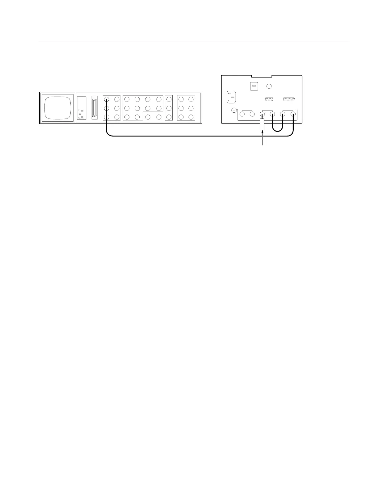
1720/1721 (rear)
Black burst
75W Termination
1410–Series (rear)
Figure 5-2: Loop-through connection of black burst signal to both EXT REF and CH-B.
b. Use the 1720/1721 PHASE control to place the burst vector tip(s) on the
graticule target(s).
c. Remove the 75Ω terminator from CH-B.
d. CHECK – for stable display in both EXT and INT reference modes.
e. Triple terminate CH-B, using three 75Ω terminators.
f. CHECK – for a stable display in both EXT and INT reference modes.
g. Disconnect the black burst signal and remove two of the terminators
from CH-B. Remove the cable that connects CH-B and EXT.
4. Check Demodulator Channel Bandwidth
REQUIREMENT – Upper –3 dB point: F
SC
+(400 kHz to 600 kHz).
Lower –3 dB point: F
SC
–(400 kHz to 600 kHz).
a. Set the 1720/1721 MODE to VECTOR and REF to EXT.
b. Connect the Leveled Sine Wave Generator to the CH-B INPUT.
c. Adjust the Sine Wave Generator frequency to 3.58 MHz NTSC and
PAL-M (4.43 MHz PAL). Adjust the Sine Wave Generator amplitude so
that the circle overlays the vector graticule circle.
d. Decrease the Sine Wave Generator frequency until the perimeter of the
circle touches the –3 dB (70%) point gaps on the vertical graticule axis.
See Figure 5-3.

 Loading...


