Maintenance
1720/1721
6–5
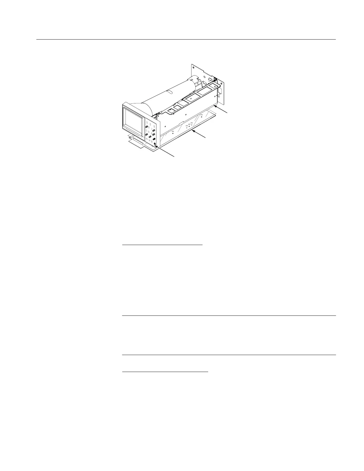
A2 Front Panel Board
A3 Main Board
A1 Power Supply Board
Figure 6-1: Circuit board assembly locations
There are two separate parts lists in this manual. The Replaceable Electrical
Parts list is in Section 8, which precedes the schematic diagrams and circuit
board illustrations. The Replaceable Mechanical Parts list (Section 10),
accompanied by exploded view drawings, follows the schematic diagrams and
circuit board illustrations.
Replaceable Electrical Parts
. This list is arranged by assembly as designated
in ANSI Standard Y32.16–1975. The list begins with the part numbers for the
major assemblies (etched circuit boards). Each circuit board is identified by an
A# (assembly number).
The circuit numbers of the individual components in the parts list is made up by
combining the assembly number with the individual circuit number. EXAM-
PLE: R117 on Assembly (circuit board) A3 is listed in the Replaceable
Electrical Parts list as A3R117.
NOTE. Check Parts Lists:
Always consult the parts list and “Change Information” for part numbers and
descriptions before ordering replacement parts. Some parts may have been
replaced in an individual instrument.
Replaceable Mechanical Parts
. This list is arranged so that it corresponds to
the exploded view drawings for major instrument components. The list and
exploded view drawings comprise Section 10 of this manual. An Accessories
Illustration and accompanying parts list is also included in this section.
Signals and power supply voltages are passed through the instrument with a
system of interconnecting cables. The connector holders on these cables have
Parts Lists
Major Assembly
Interconnection

 Loading...


