Maintenance
1720/1721
6–13
3. Z-Axis Amplifier Check
a. Unsolder and lift one end of R8.
b. Power up the power supply.
c. Using the digital multimeter, measure the voltage between TP1 and the
collector of Q4. It should be approximately +10 V.
d. Short together the base and emitter of Q5. The collector of Q4 should be
approximately +100 V.
e. Reconnect the lifted end of R8.
4. Grid Drive Check
a. Turn off the power supply. Use the diode check on the digital multime-
ter to test CR1, CR2, CR3, CR5, and CR6 for shorts.
b. Power up the power supply.
c. Using the digital multimeter, measure the voltage between TP1 and the
cathode of CR5. It should vary between approximately +75 and +200 V
as R58 (CRT Bias) is adjusted.
d. Connect the oscilloscope probe to the anode of CR5 and the probe
ground to TP1. The signal should be a clipped sine wave of +75 to +200
V p-p.
5. High Voltage Oscillator Check
a. Connect the oscilloscope probe to T1 pin 3 (Q6 collector) and the probe
ground to TP1. Power up the supply. The signal should be a +60 V p-p,
22 kHz sine wave.
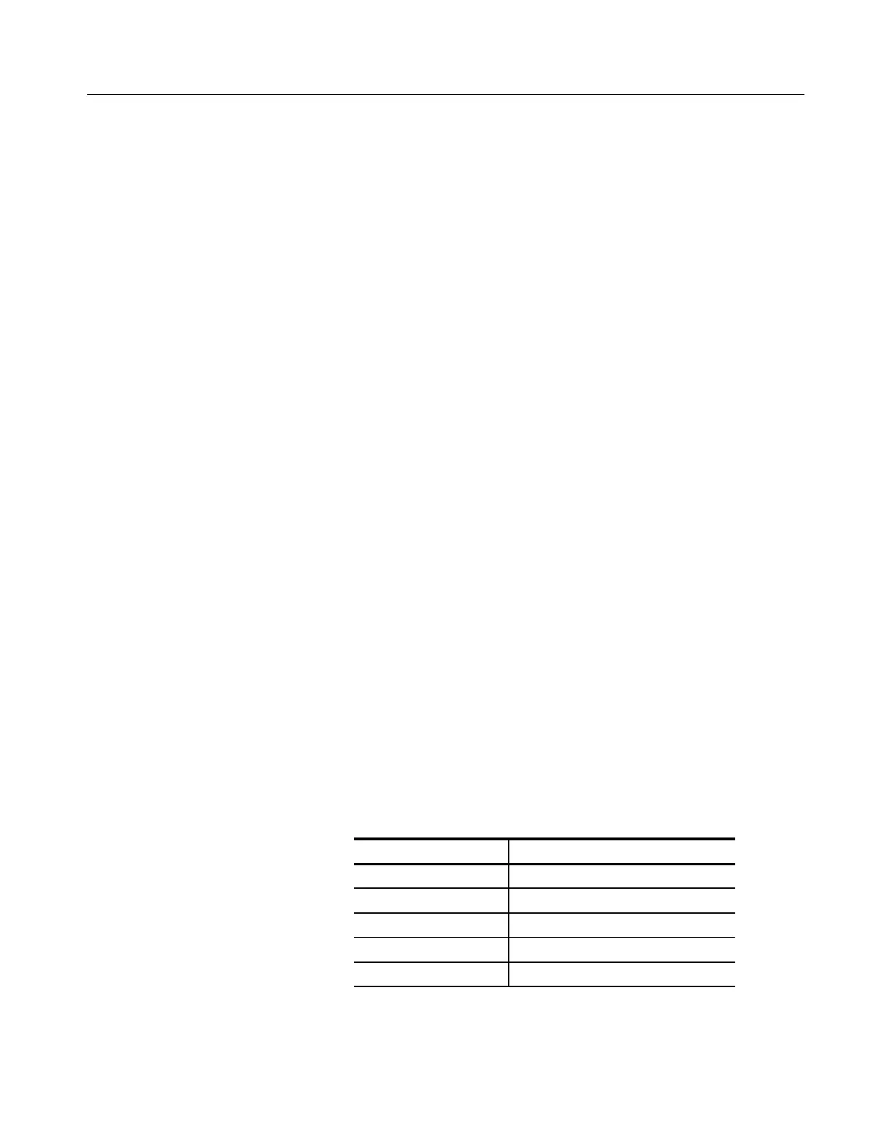
b. Check the voltages listed in Table 6–6 using the digital multimeter:
Table 6–6: High Voltage Oscillator Test Points
Circuit Location Voltage
T1, pin 4 Approximately +40 V
T1, pin 13 Less than +2 V
U2, pin 2 Approximately +4.8 V
U2, pin 6 +4 to +11 V
CR9, cathode Approximately +100 V

 Loading...


