Checks and Adjustments
5–18
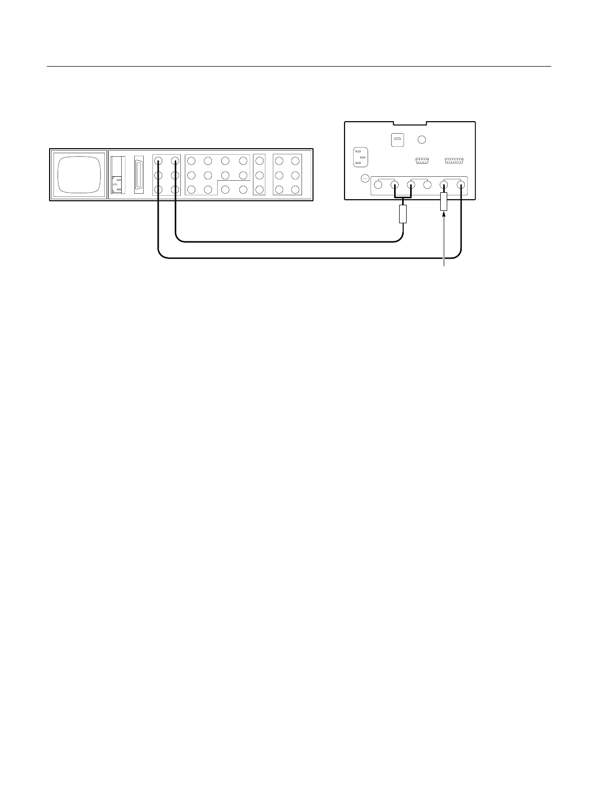
1720/1721
1720/1721 (rear)
Black burst
75W Termination
1410–Series (rear)
Color bar
75W Terminator
Figure 5-8: Starting connections for the adjustment procedure.
Connect the Function Generator to the 1720/1721 XY INPUT. See Figure 5-1
for a diagram of how to hook up the 15-pin D-type connector to calibrate the
1720/1721 Vectorscope. Set the Function Generator frequency to 50 kHz.
Preset the 1720/1721 front panel as follows:
MODE VECT
REF INT
INPUT CH-A
VARIABLE Off
BARS 75%
AUXILIARY Off
PAL/+V (1721 Only) PAL
INTENSITY As desired.
FOCUS As desired.
SCALE As desired.
Allow 20 minutes of warm-up time, at normal room temperature (approximately
25° C), before making any adjustments to the instrument.
Adjustment Procedure Short-Form Reference
The short-form reference table is intended for those who are familiar with the
complete Adjustment procedure. Step and page numbers provide easy cross-ref-
erence to the long-form procedure on the following pages.
Front-Panel Presets

 Loading...


