Checks and Adjustments
1720/1721
5–17
Adjustment Procedure
This procedure is divided into two parts. The first, a short form, is an outline of
the full procedure. The full procedure is more detailed and is intended to lead a
technician through each step. The short form can be used as a short cut for those
familiar with the instrument calibration or an index of steps in the longer form.
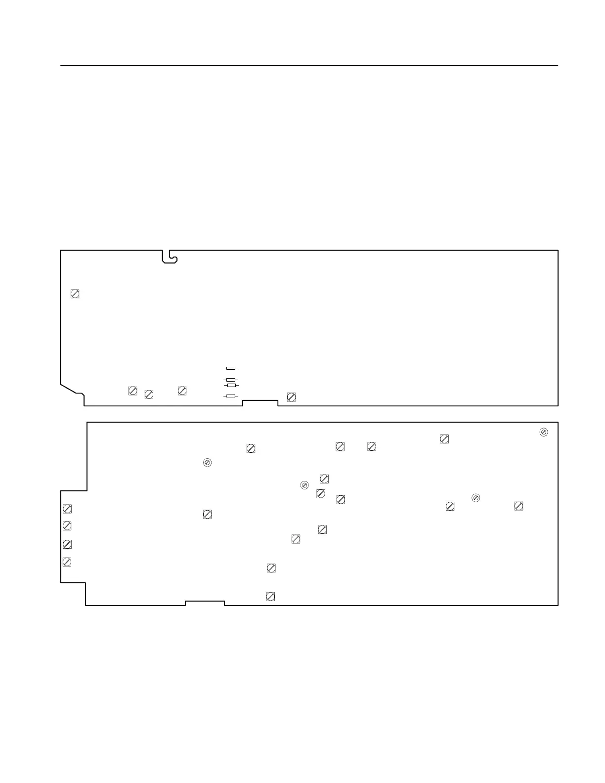
Figure 5-7 shows the adjustment locations. (Note that R453 +V Overlay is only
in the PAL and PAL-M, 1721 Vectorscopes.) This illustration also contains the
step number of the adjustment as a cross-reference.
A1 Pwr Supply Bd
A3 Main Bd
FOCUS
R11 (3)
GEOM
R45 (3)
ASTIG
R49 (3)
CRT BIAS
R58 (2)
W4 +15 V
W1 +5 V
W3 –15 V
+5 V ADJ R99 (1)
C484 (10)
R534 (11)
C235 (6)
Front
R502
R602
R702
R703
R846 (9)
R948 (9)
R244 (15)
R178 (14)
R460 (13)
R355 (7)
R655 (13)
C198
(8)
R594 (8)
R578 (4)
R653 (7)
C453 (12)
R267 (5)R259 (5)
R453
(12)
W2 +40 V
Figure 5-7: Adjustment and test point locations for 1720/1721 Vectorscope. Numbers in parentheses correspond to
adjustment steps.
Connect the black burst signal to the 1720/1721 EXT REF INPUT. Connect the
color bar signal to the 1720/1721 CH-A INPUT and CH-B INPUT through a
dual input coupler with an in-line 75Ω terminator. See Figure 5-8.
Signal Connections

 Loading...


