Theory of Operation
4–20
1720/1721
+
–
–
+
From peak detector
R83
10.0K
R84
24.9K
R79
49.9K
R101
49.9
2R
R
+2.5V
R96
0.51
Q9
Latch
R87
22.1
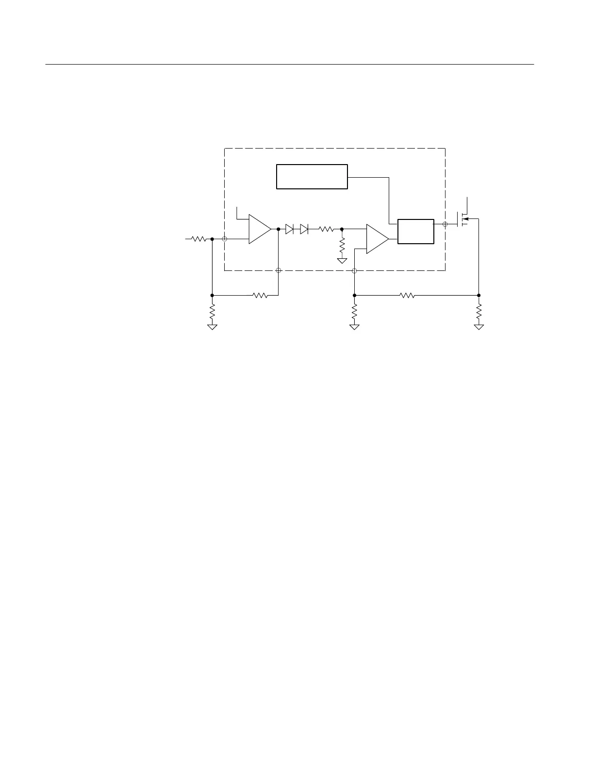
Simplified pulse width modulator
Oscillator
Switcher
mosfet
2
13
6
U5 is a current-mode pulse width modulator (PWM). A current-mode PWM
uses two feedback loops. The inner current-feedback loop directly controls the
switcher mosfet peak current. The outer voltage-feedback loop programs the
inner loop peak current trip point.
U5 pin 2 is the inverting input of an internal op-amp. The non-inverting input is
set to 2.5 V by an internal voltage reference. Current from the peak detector
flows through R83, R84, and R76. R84 provides a 100 mA offset. The voltage
at U5 pin 1 will vary in order to maintain U5 pin 2 at 2.5 V.
The voltage at U5 pin 1 is modified by an internal circuit and sets the trip point
of the internal comparator. U5 pin 3 is the external input to the comparator. R88
and C52, connected to U5 pin 4, set the internal oscillator to 80 kHz.
The circuit works as follows: The oscillator resets the latch and U5 pin 6 goes
high, turning the switcher mosfet on. The current through the switcher mosfet
increases, causing the voltage across R96 to increase. This voltage is divided by
R87 and R101, and is applied to the comparator (pin 3). When the voltage at U5
pin 3 reaches the comparator trip point, the latch toggles and the switcher mosfet
is turned off. This process is repeated at an 80 kHz rate.
C58 increases the PWM noise immunity by rolling the internal op-amp
frequency response. R82 holds the switcher mosfet off as the circuit is powering
up. R81 slows the turn-on of the switcher mosfet while CR27 speeds up the turn
off.
The three output windings supply four output voltages. Each output is rectified
by a single diode and filtered by an LC pi filter.
Pulse Width
Modulator
Output Filters

 Loading...


