Maintenance
1720/1721
6–9
determining which section of the power supply the problem is in. Apply ac
power and turn on the power supply. From Table 6–2, determine which
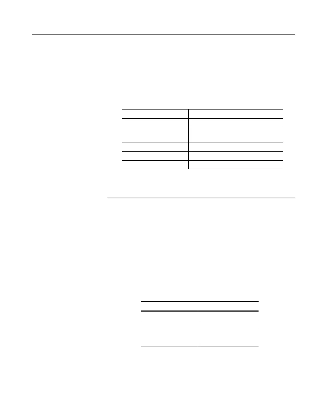
symptom the power supply exhibits and refer to the corresponding procedure.
Table 6–2: Power Supply Fault Symptoms
Symptom Procedure
Line fuse open Rectifier/Switcher Check (Low Volts)
Power Supply cycles OFF/ON Output Check (Low Volts), or
High Voltage Oscillator Check (High Volts)
Does not power up Control Circuit Check (Low Volts)
+5 V not regulating Error Amplifier Check (Low Volts)
Improper CRT display High Volts Supply
NOTE. Low Volts Supply Load:
A 20W, 2 watt resistor should be used as a load for the Low Volts Supply.
Disconnect J4 and connect the 20W resistor between W1 (+5 V) and TP1
(secondary ground).
1. Preliminary Checks
a. A properly functioning and loaded Low Volts supply will output the
voltages listed in Table 6–3. Use the DMM to measure the voltages
between TP1 and the voltage test points. If the supply is not regulating
properly, continue with the procedure.
Table 6–3: Low Volts Supply Voltages
Test Point Voltage Range
W1 – (+5 V) +4.88 to +5.12 V
W4 – (+15 V) +14.0 to +16.0 V
W3 – (–15 V) –14.0 to –16.0 V
W2 – (+40 V) +39.0 to +41.0 V
Low Volts Supply

 Loading...


