Operating Instructions
1720/1721
2–23
0°
10°
df
10°
20%
dG
YL
10%
dG
yl
75% 100%
100%
75%
WITHOUT
SETUP
WITH
SETUP
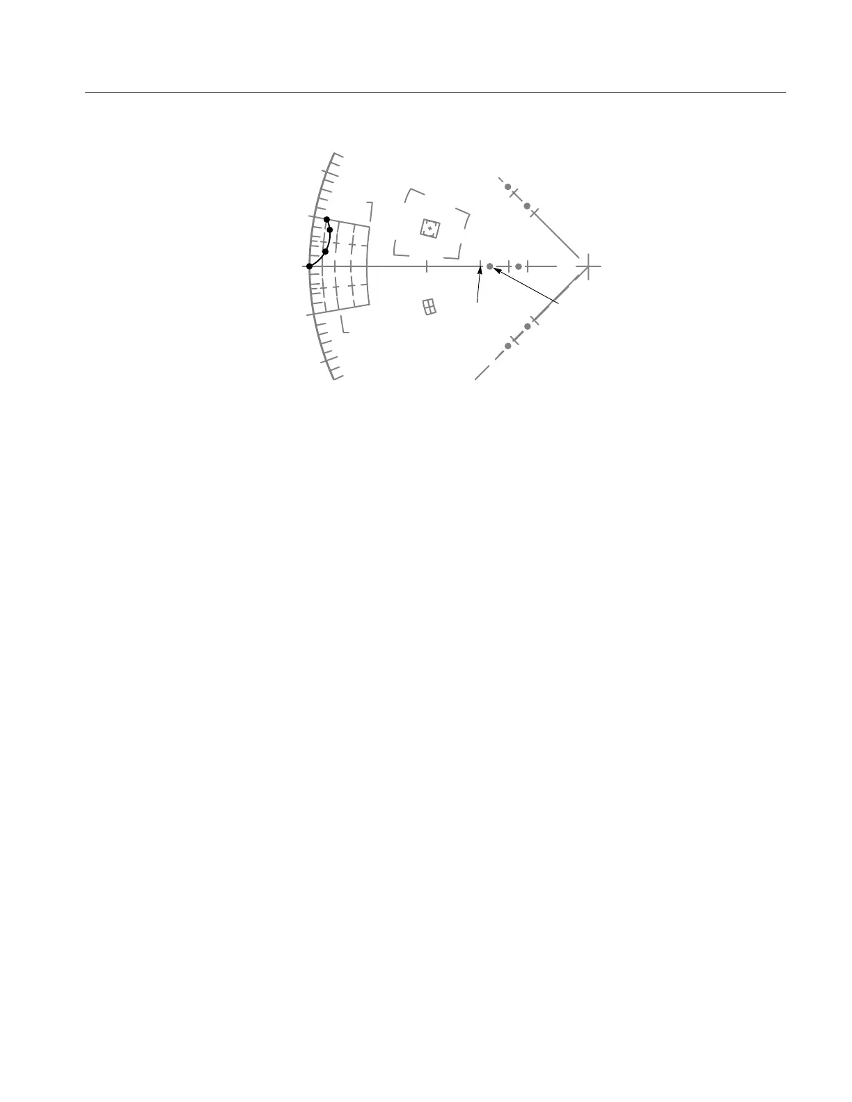
Figure 2-17: A simulation of a part of the 1720 graticule showing the differential
phase and gain measurement scales with approximately 10° differential Phase (dP).
Differential gain (dG) and differential phase (dφ) measurements can be made
using the graticule markings located at the outer edge of the B-Y axis (1720) or
–U axis (1721). See Figure 2-18 for a differential gain measurement illustration
and Figure 2-17 for a differential phase measurement illustration.
High Resolution Differential Phase Measurement –– The DEMOD OUT from
the 1720/1721 can be used to drive one of the inputs to a 1730-Series Waveform
Monitor for improved measurement resolution. This measurement requires a
modulated ramp or staircase signal with the 1720/1721 gain normalized so the
chrominance amplitude is on the compass rose.
The 1730-Series must have the DC REST OFF and the VERTICAL GAIN at
X5. Once these conditions are set up, using 1 LINE SWEEP makes each major
vertical division of the 1730-Series graticule equal to 2°, when referenced to the
sweep origin.

 Loading...


