Maintenance
6–6
1720/1721
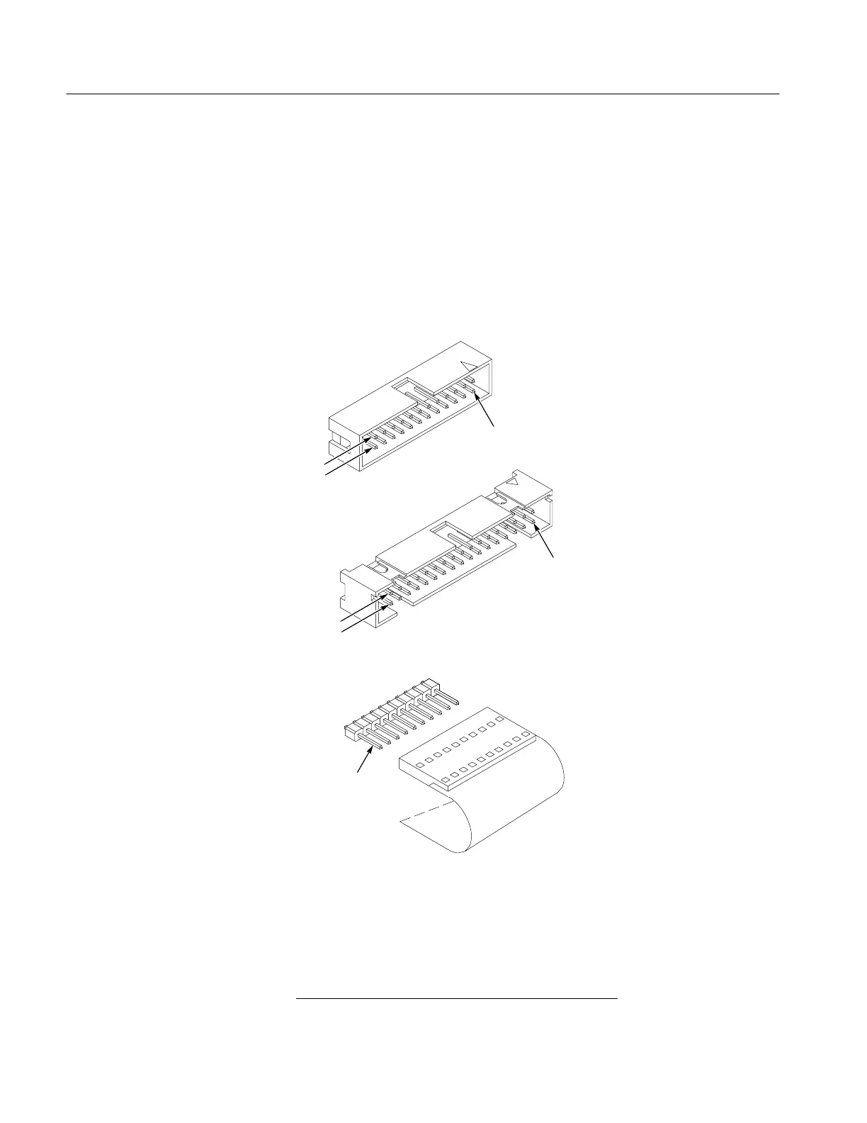
numbers that identify terminal connectors; numerals are used from 2 up. A
triangular key symbol is used to identify pin 1 on the circuit board and the
connector to assist in aligning the connector with correct square pins. Figure 6-2
shows the numbering scheme (and the triangular marking) on the connector and
the marking on the etched circuit board.
A pin replacement kit including necessary tools, instructions, and replacement
pins is available from Tektronix, Inc. Contact a Tektronix field office or
representative for assistance in ordering this kit.
CKT Bd mounted pins
Moveable 10–pin plug
Square pin connector on
power supply CKT bd
Pin 1
24 and 34 pin CKT bd
connectors on
Main CKT Board
Row A
Row B
Pin 1
Row A
Row B
Pin 1
Figure 6-2: Multiple pin connectors used in the 1720/1721 Waveform Monitors
The following procedure is designed to assist in isolating problems, which in
turn expedites repairs and minimizes down time.
1. Ensure that the malfunction exists in the instrument
. This is done by making
sure that the instrument is operating as intended by Tektronix (see Operating
General Troubleshooting
Techniques

 Loading...


