Specification-2465 Operators
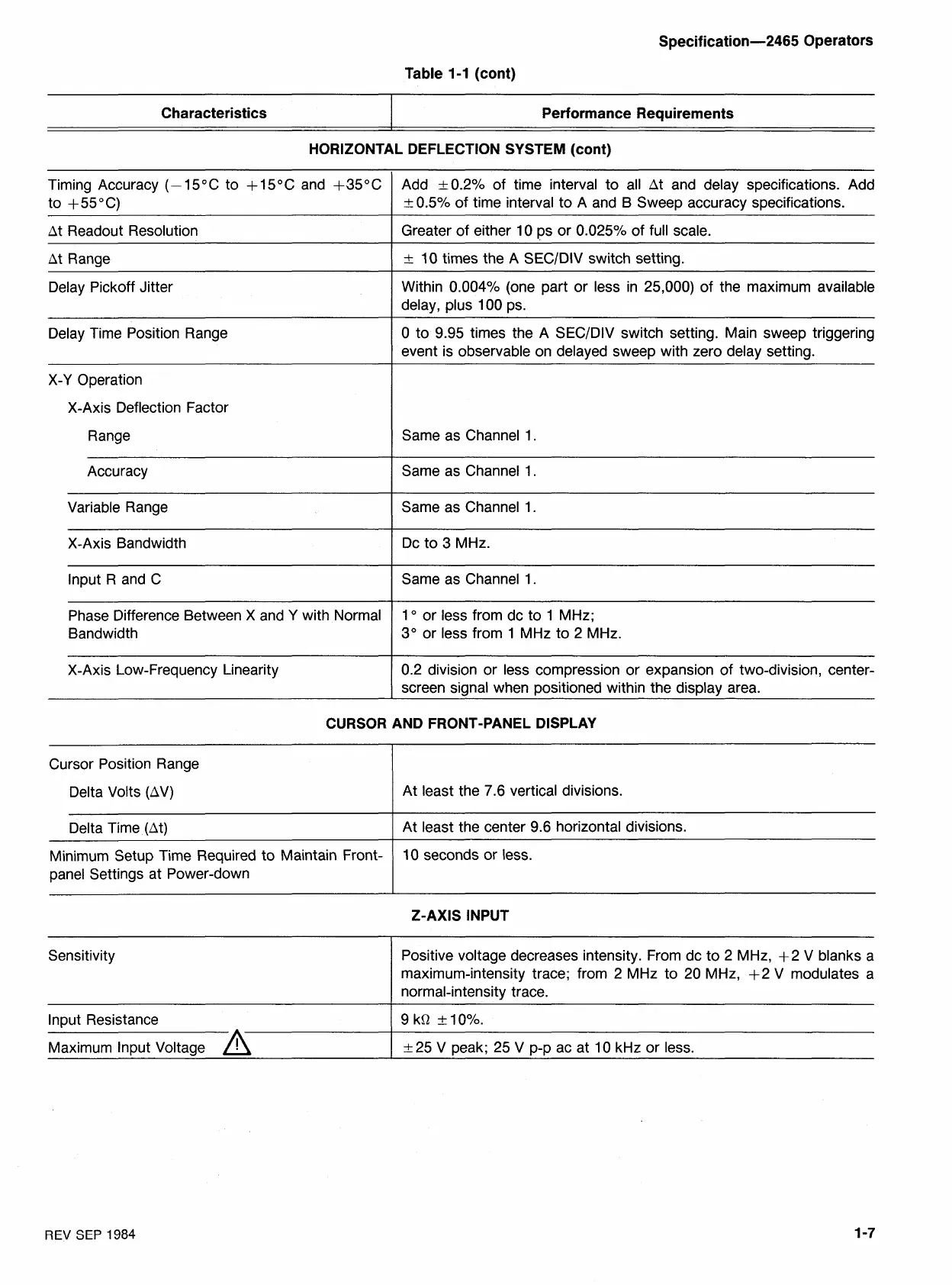
Table 1-1 (cont)
Timing Accuracy
(-1 5°C
to
+
l5OC
and
+35OC
to
+55OC)
Characteristics
At Readout Resolution
Performance Requirements
At Range
HORIZONTAL DEFLECTION SYSTEM (cont)
Delay Pickoff Jitter
Delay Time Position Range
X-Y Operation
X-Axis Deflection Factor
Range
Accuracy
Variable Range
X-Axis Bandwidth
lnput R and
C
Phase Difference Between X and Y with Normal
Bandwidth
X-Axis Low-Frequency Linearity
Add
+0.2%
of time interval to all At and delay specifications. Add
20.5%
of time interval to A and B Sweep accuracy specifications.
Greater of either
10
ps or
0.025%
of full scale.
+_
10
times the
A
SECIDIV switch setting.
Within
0.004%
(one part or less in
25,000)
of the maximum available
delay, plus
100
ps.
0
to
9.95
times the
A
SECIDIV switch setting. Main sweep triggering
event is observable on delayed sweep with zero delay setting.
Same as Channel
1
Same as Channel
1.
Same as Channel
1.
Dc to
3
MHz.
Same as Channel
1.
1
O
or less from dc to
1
MHz;
3"
or less from
1
MHz to
2
MHz.
0.2
division or less compression or expansion of two-division, center-
screen signal when positioned within the display area.
CURSOR AND FRONT-PANEL DISPLAY
Cursor Position Range
Delta Volts (AV)
At least the
7.6
vertical divisions.
Delta Time (At)
I
At least the center
9.6
horizontal divisions.
Minimum Setup Time Required to Maintain Front-
panel Settings at Power-down
10
seconds or less.
Z-AXIS INPUT
Sensitivity
Positive voltage decreases intensity. From dc to
2
MHz,
+2
V blanks a
maximum-intensity trace; from
2
MHz to
20
MHz,
+2
V modulates a
normal-intensity trace.
Input Resistance
1
9
kR
t
1O0/0.
Maximum Input Voltage
A
1
k25
V peak;
25
V p-p ac at
10
kHz or less.
REV
SEP
1984

 Loading...


