Specification-2465 Operators
Table
1-1
(cont)
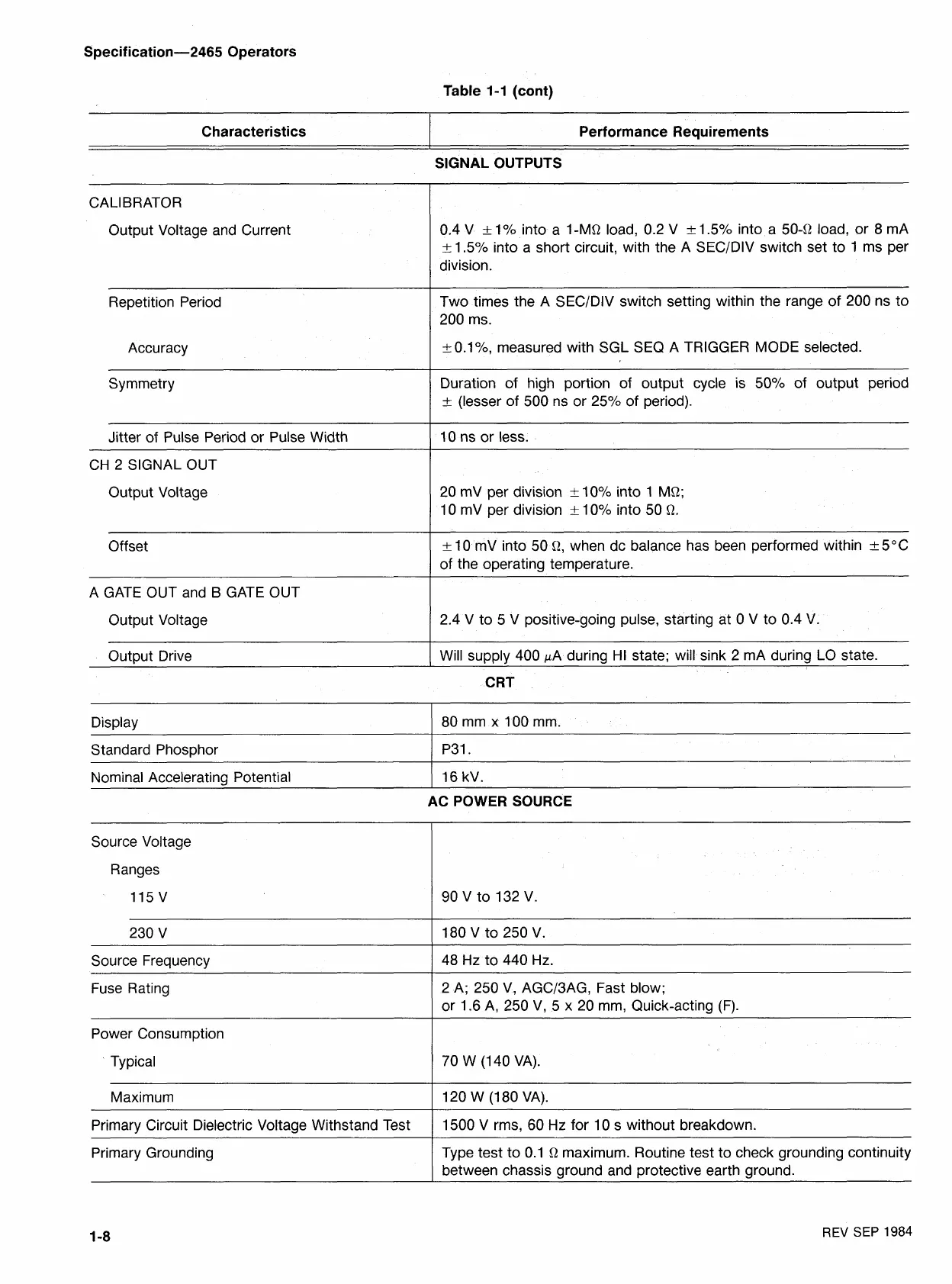
Characteristics
CALIBRATOR
Output Voltage and Current
Repetition Period
Accuracy
Symmetry
Jitter of Pulse Period or Pulse Width
CH
2
SIGNAL OUT
Output Voltage
Offset
A GATE OUT and
B
GATE OUT
Output Voltage
Output Drive
Performance Requirements
SIGNAL OUTPUTS
0.4
V
t-
1%
into a
I-MQ
load,
0.2
V
k
1.5%
into a
504
load, or
8
mA
k
1.5%
into a short circuit, with the A SECIDIV switch set to
I
ms per
division.
Two times the A SECIDIV switch setting within the range of
200
ns to
200
ms.
t-
0.1%
measured with SGL SEQ A TRIGGER MODE selected.
Duration of high portion of output cycle is
50%
of output period
k
(lesser of
500
ns or
25%
of period).
10
ns or less.
20
mV per division
~t_
10%
into
1
MQ;
10
mV per division
k
10%
into
50 Q.
k
10
mV into
50
Q,
when dc balance has been performed within
-+
5°C
of the operating temperature.
2.4
V to
5
V positive-going pulse, starting at
0
V to
0.4
V.
Will supply
400
PA during HI state; will sink
2
mA during LO state.
CRT
Source Voltage
Display
Standard Phosphor
Nominal Accelerating Potential
Ranges
80
mm x
100
mm.
P31.
16
kV.
230
V
Source Frequency
Fuse Rating
AC POWER SOURCE
Power Consumption
Typical
Maximum
Primary Circuit Dielectric Voltage Withstand Test
Primary Grounding
-
--
-
48
Hz to
440
Hz.
2
A;
250
V, AGC/3AG, Fast blow;
or
1.6
A,
250
V,
5
x
20
mm, Quick-acting (F).
70
W
(1 40
VA).
120
W
(I 80
VA).
1500
V rms,
60
Hz for
10
s without breakdown.
Type test to
0.1
Q
maximum. Routine test to check grounding continuity
between chassis ground and protective earth ground.
REV
SEP
1984

 Loading...


