TM 11-6625-2735-14-1
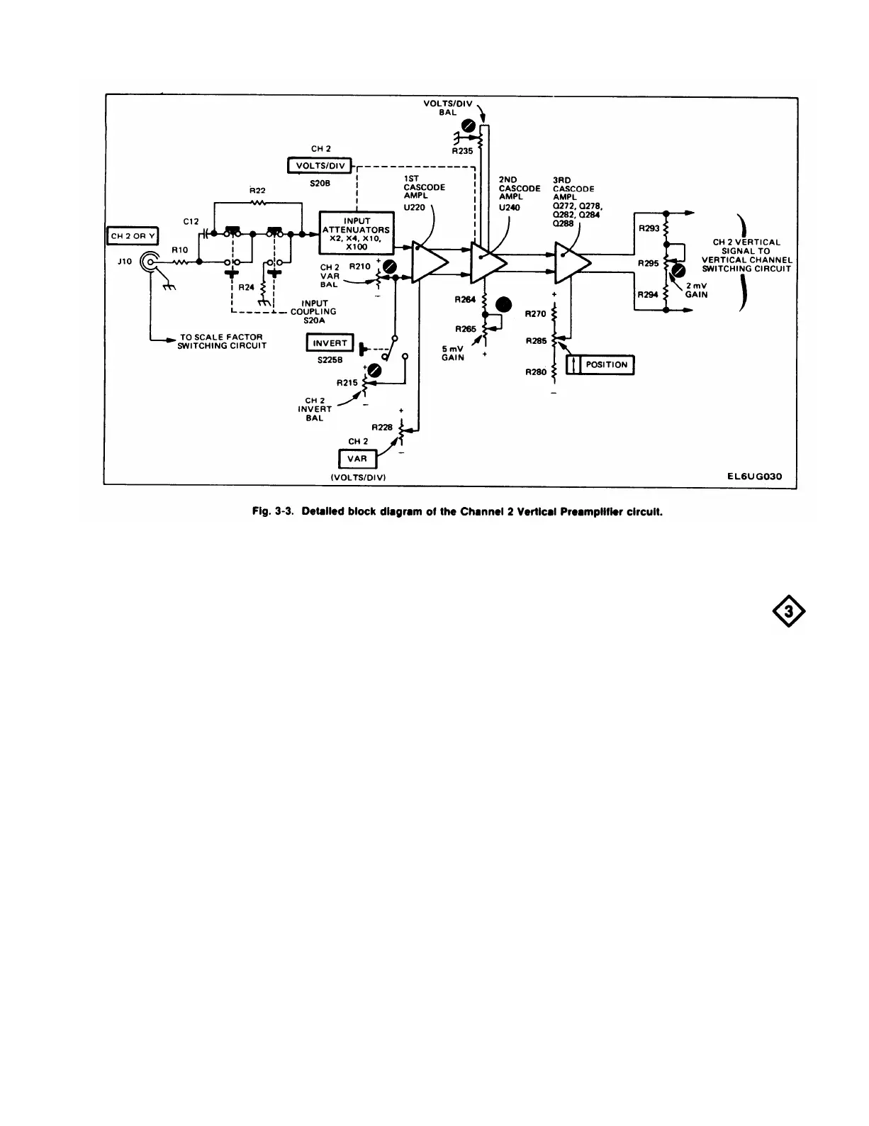
First Cascode Amplifier
Basically, the First Cascode Amplifier stage in Channel
2 operates as described for the First Cascode Amplifier
stage in Channel 1. However, the Channel 2 First Cascode
Amplifier also contains the INVERT switching function.
This allows the Channel 2 signal to be inverted as
displayed on the CRT. The INVERT switch, when pushed,
changes the biasing on the output transistors of U220 so
that the normally inactive transistors are now carrying the
signal. Since their outputs are cross-coupled from side to
side the output signal is of opposite polarity to that
available in the normal (button out) position of the
INVERT switch. The Channel 2 Invert Balance adjustment
R215 adjusts the DC. balance of the stage to eliminate
baseline shift in the display when switching from a normal
to an inverted display.
VERTICAL CHANNEL SWITCHING
General
The Vertical Channel Switching circuit determines
whether the Channel 1 or the Channel 2 Preamp signal or
both will be connected to the Vertical Output Amplifier
circuit. In the ALT and CHOP modes of operation, both
channels are alternately displayed on a shared-time basis.
The Vertical Channel Switching circuit also provides
several internal trigger signals to the Trigger Generator
circuits, the Channel 2 VERT SIGNAL OUT signal to a
connector on the rear panel, and the chopped blanking
signal to the Z Axis Amplifier. Fig. 3-4 shows a detailed
block diagram of the Vertical Channel Switching circuit. A
schematic of this circuit is shown on Diagram 3 at the rear
of this manual.
3-7

 Loading...


