TM 11-6625-2735-14-1
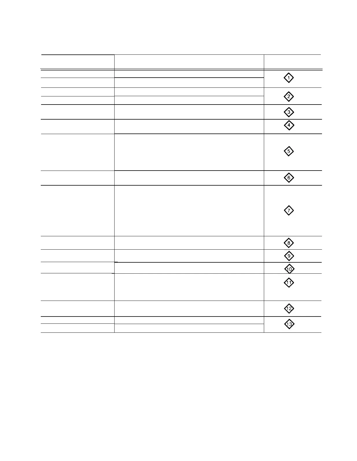
TABLE 4-1
Circuit Number-to-Diagram Locator
Circuit Number
Series
Diagram
Name of Circuit Number
10 — 49
100 — 199
CH 1 ATTENUATORS
CH 1 VERTICAL PREAMP
10 — 69
200
— 299
CH 2 ATTENUATORS
CH 2 VERTICAL PREAMP
300 — 439
VERTICAL CHANNEL SWITCHING
440 — 499 VERTICAL OUTPUT AMPLIFIER
500 — 570, R579
(See LV POWER SUPPLY
for more 500-series numbers)
660 — 679
700 — 709
710 — 786, R789
A TRIGGER GENERATOR
B TRIGGER GENERATOR
571 — 629
640 — 649
680 — 699
787 — 829
1492 — 1499 (See LV
POWER SUPPLY for more
1490-series numbers)
SWEEP AND Z AXIS LOGIC
900 – 1049
SWEEP GENERATORS
TIMING AND HORIZONTAL DISPLAY SWITCHING
HORIZONTAL AMPLIFIER
1050 — 1099
1100– 1269
C507, R507, C508, R508, R529
C1335, LR1335, C1336, LR1336
1400 — 1490
R1495, Q1494, Q1496, Q1497
LV POWER SUPPLY
1300– 1399
CRT CIRCUIT
1500 – 1519
1690 – 1699
CALIBRATOR
FAN CIRCUIT
Diode Color-Code. The cathode end of each glass-
Semiconductor Lead Configuration.
Fig 4-3 shows the
encased diode is indicated by a stripe, a series of stripes,
lead configuration for the semiconductors used in this
or a dot. For most silicon or germanium diodes with a
instrument, as viewed from the bottom of these miconduc-
series of stripes,
the color-code identifies the three
tors
significant digits of the Tektronix Part Number using the
resistor color-code system (e g , a diode color-coded pink
— or — blue—, brown —gray—green indicates Tektronix
Part No 152-0185-00). The cathode and anode ends of
Troubleshooting Equipment
metal-encased diodes can be identified by the diode
The following equipment is useful for troubleshooting
symbol marked on the body.
in the 475.
4-7

 Loading...


