TM 11-6625-2735-14-1
Delaying Sweep Generator
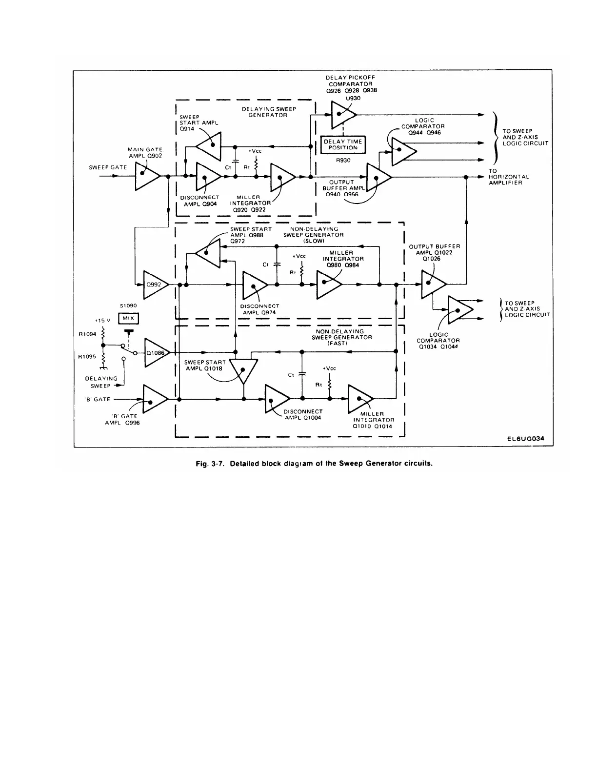
Basically the Delaying Sweep Generator is composed
of Q904, Q920, Q922, and Q914. This generator runs in the
A INTEN, MIX, and B DLY’D positions of the HORIZ
DISPLAY switch and generates the A portion of the
display In these modes the sweep rate is selected by the A
TIME/DIV switch (skirt knob).
Main Gate Amplifier
Q902 is the Main Gate Amplifier stage. The negative-
going Main Gate waveform from the Sweep Logic circuit is
applied to the base of Q902. The amplified and inverted
waveform at the collector of C902 is applied to the
Delaying Sweep Generator (through CR903), or to both of
the Non-Delaying Sweep Generators (through Q992) in
the A sweep mode. This initiates sweep generation.
Sweep Disconnect Amplifier
Q904 is the Sweep Disconnect Amplifier. The biasing
on the base of this stage determines whether the Delaying
Sweep Generator will run. In the A position of the HORIZ
DISPLAY switch, the anode of CR907 is connected to +5
volts through R908 and the HORIZ DISPLAY switch
circuit. This biases the base of Q904 far enough positive
that the positive-going gates on the emitter cannot turn off
Q904 Q904 therefore conducts all of the timing current
through R905, R904, and timing resistor R
t
, charging
timing capacitance C
1
. When the HORIZ DISPLAY switch
is in any position other than A, CR907 is reverse-biased,
which lets the base of Q904 be biased at a level that will
allow the positive-going gates on the emitter of Q904 to
interrupt the current flow through Q904 When Q904 turns
off, the timing current starts to discharge timing
capacitance C
t
.
3-17

 Loading...


