TM 11-6625-2735-14-1
In the A INTEN position of the HORIZ DISPLAY switch,
+5 volts is connected to the anode of CR1049. This
forward biases CR1044, which sets the collector of Q1044
at approximately +0.7 volts. This keeps CR1046 reversed
biased and prevents completely blanking the CRT at the
end of the Non-Delaying Sweep portion of the display. In
the A INTEN, MIX, and B DLY’D positions of the HORIZ
DISPLAY switch, –8 volts is connected to the anode of
CR1036 through R1090. This turns off the diode gate
(CR1034 and CR1037) preventing a Non-Delaying Sweep
end-of-sweep pulse output from Q1034 collector which
would terminate the Delaying Sweep. This pulse is
allowed to reset the Non-Delaying Sweep through Q788.
In the A position of the HORIZ DISPLAY switch (knobs
locked), a more positive voltage is connected to the anode
of CR1036. This enables CR1034 and CR1037, thus
allowing the Main Sweep end-of-sweep pulse to pass to
the Sweep Logic circuit. The logic levels are generated by
the HORIZ DISPLAY switch, Q1062, Q1066 and Q1099.
TIME/DIV Functions (Knobs Unlocked)
Normally, when the HORIZ DISPLAY switch is set to A,
the Non-Delaying Sweep Generator is being used to
knob of TIME/DIV) is unlocked and set to a faster sweep
rate, the Non-Delaying Sweep Generator is then being
used to display A Sweep. In this mode, the A TIME/DIV
(skirt knob) must be used to control A Sweep rates.
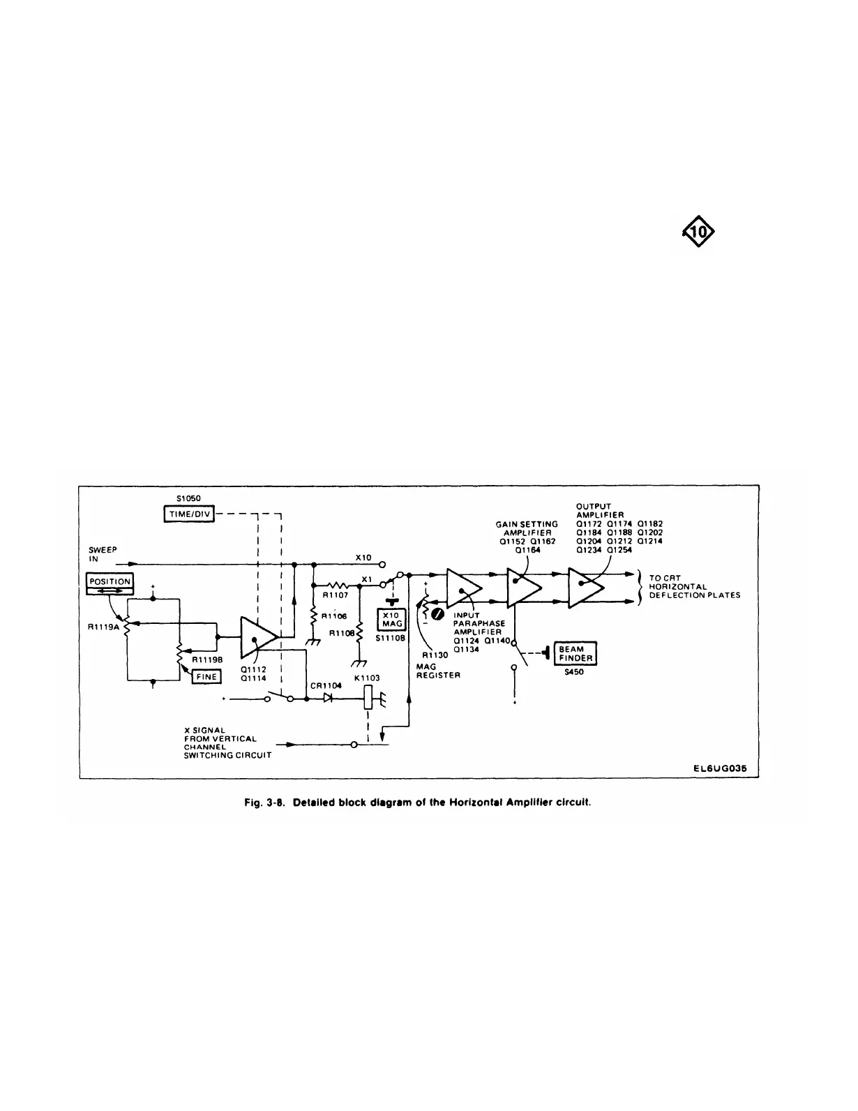
HORIZONTAL AMPLIFIER
General
The Horizontal Amplifier circuit provides the output
signals to the CRT horizontal deflection plates. The signal
applied to the input of the Horizontal Amplifier is deter-
mined by the TIME/DIV switch. The signal can be a
sawtooth waveform generated within the instrument, or
some external signal applied to the CH 1 OR X input
connector (X-Y mode of operation). The Horizontal
Amplifier also contains the X10 magnifier, horizontal
positioning controls, and some beam finder circuitry. Fig.
3-8 shows a detailed block diagram of the Horizontal
Amplifier circuit. A schematic of this circuit is shown on
display A Sweep. When the DLY’D SWEEP control (inner Diagram 10 at the rear of this manual.
3-20

 Loading...


