TM 11-6625-2735-14-1
Troubleshooting the L.V. Power Supplies. Incorrect
operation of all circuits often indicates trouble in the
power supply. Check first for correct voltage of the
individual supplies. A defective component elsewhere in
the instrument can appear as a power-supply trouble and
may also affect the operation of other circuits. Table 4-2
lists the tolerances of the power supplies in this instru-
ment. Check or repair the power supplies in the sequence
specified in Table 4-2. These voltages are measured
between the power-supply test points and ground. If a
power-supply voltage is within the listed tolerance, the
supply can be assumed to be working correctly. If outside
the tolerance, the +50-volt supply may be misadjusted or
other supplies may by operating incorrectly. Use the
procedure given in TB 11-6625-2735-35-1 to adjust the
+50-volt supply if adjustment is necessary.
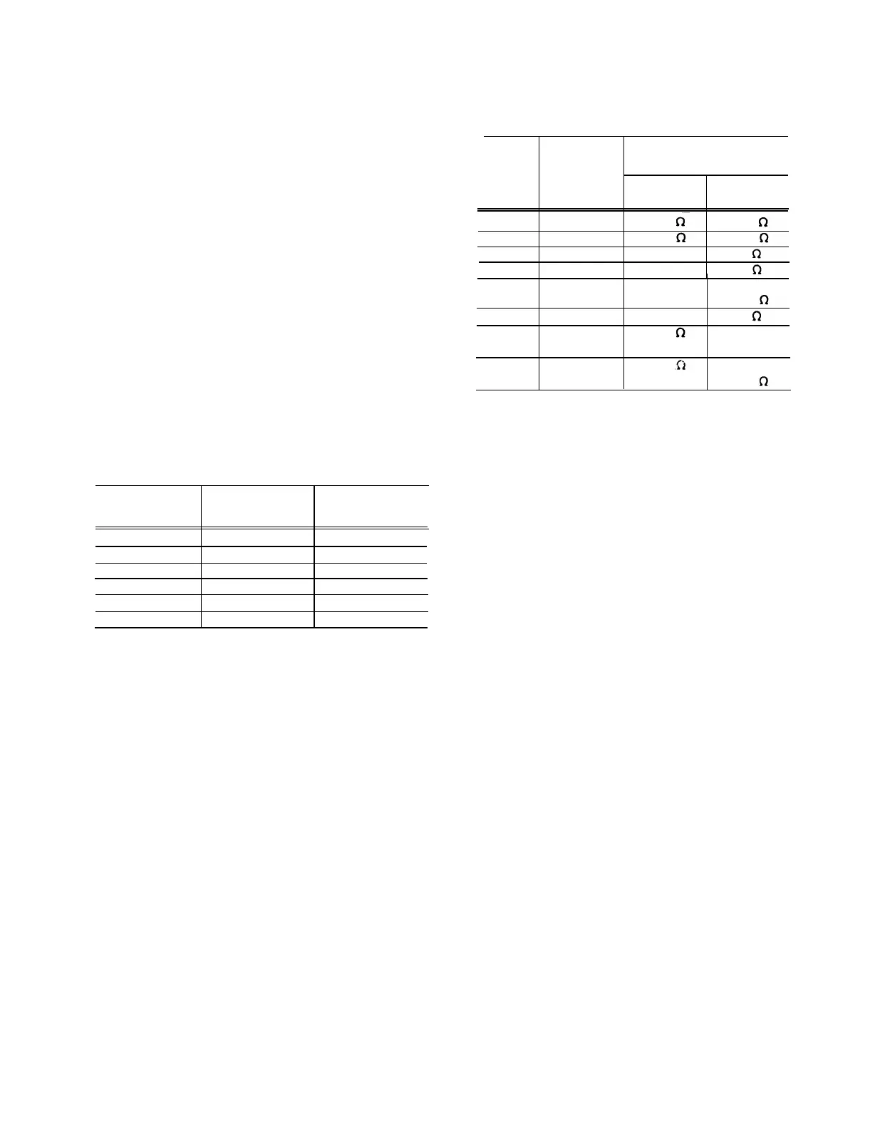
TABLE 4-3
Power Supply Resistance Check
1
Typical Resistance
To Ground’
Ohmmeter + Lead
– Lead
Supply
Scale
2
At Supply
At Supply
+110V
20 K
11 k
9.3 k
+50 V
20 K
2.7 k
2.7 k
+15V
2K
63
63
4-5
V
2K 46
46
—15 V
2K
480
- - - - -
20 K
- - - - -
10 k
-8 V
2 K
32 32
UNREG
20 K
14 k
- - - - -
+50 V
2K
- - - - -
500
+105/
20 K
12 k
- - - - -
160 V
2K
-----
1 k
TABLE 4-2
Power Supply Tolerance and Ripple
Typical Ripple
Power Supply
Tolerance
(peak-to-peak)
+50V
0.5% (250 mV)
2 mV
+110V
3% (3.3 V)
1 V
+15V
1.5% (225 mV)
2 mV
+5V
1 .5% (75 mV)
2 mV
-15V
1.5% (225 mV)
2 mV
-8V
1.5% (120 mV)
2 mV
If any of the supplies are shorted to ground, repair them
until normal resistance readings are obtained. Connect
the instrument to the correct power source and check the
supplies for proper voltages listed in Table 4-2. If two or
more of the individual supplies have incorrect voltages,
repair them in the order listed in Table 4-2.
The +50 volt supply is the reference for all other
supplies and must be repaired first. The +15 volt supply
and the +5 volt supply should be working properly before
repair on the –8 volt supply or the –15 volt supply is
attempted.
Connect the 475 to a variable autotransformer. Then,
check each power supply for correct ripple with a test
When repairing a power supply in the 475 the following
oscilloscope, while varying the autotransformer
throughout the regulating range of this instrument (see
Information may be helpful. The +50-volt supply is used as
an example to identify component functions.
rear panel regulating range selector cover for regulating
range). Table 4-2 lists the typical ripple of the power
supplies in this instrument. Measure the ripple between
the power supply test points and ground.
1. Check for proper voltage and ripple from the diode
bridge rectifier (CR1412 in the +50-volt supply; check at
collector of the series regulator for any supply).
A malfunction in the power supply can be caused by
one or more supplies being shorted to ground. Check the
resistance of the individual supplies to ground against the
1
Instrument power cord should be removed from power source.
typical resistances Iisted in Table 4-3. Be sure the instru-
ment is not connected to a power source when making
2
Readings taken with a digital ohmmeter (see item 3 under
Troubleshooting Equipment in this section).
these measurements to prevent error in resistance
readings and to prevent possible meter damage.
3
Readings are normal if within 50% of listed valve.
4-15

 Loading...


