f. Wire to the –2450 test point is solid red.
g. Wire to the right-hand notch on the three-notch
ceramic-strip is white with an orange stripe.
h. Wire to pad 14 (lowest of a pair of wires between the
large high-voltage capacitors) is white with brown and
yellow stripes.
i. Wire to pad 1 (upper pad between the large high-
voltage capacitors) is white with a brown stripe.
j. Wire to second notch on the five-notch ceramic-strip
(notch containing junction of a 0.01 microfarad capacitor,
a 10-megohm resistor, and a diode) is white with brown
and red stripes.
13. Remove the three power transistor mounting-
screws from Q1468, Q1426, and Q1448 on the rear
subpanel bracket.
14. Remove the mounting screw from transistor Q1456
near the lower-rear corner of the board.
15. Remove the mounting screw from transistor Q1482
near the top-right corner of the board.
16. Remove the four hexagonal posts that mount the
high-voltage shield. Use a 3/16-inch nut driver.
17. Remove seven Main Interface board mounting-
screws.
18. Disconnect the crt anode-lead plug from the high-
voltage multiplier jack. Ground this lead to the instrument
main-chassis to remove any stored charge. Pry the
multiplier jack from its mounting clip with a medium-size
screwdriver.
TM 11-6625-2735-14-1
Perform repairs on the reverse side of the Main
Interface board, if repair is intended. To reinstall the
board, reverse the removal procedure. If intentions are to
replace the Main Interface circuit-board, continue with
this procedure.
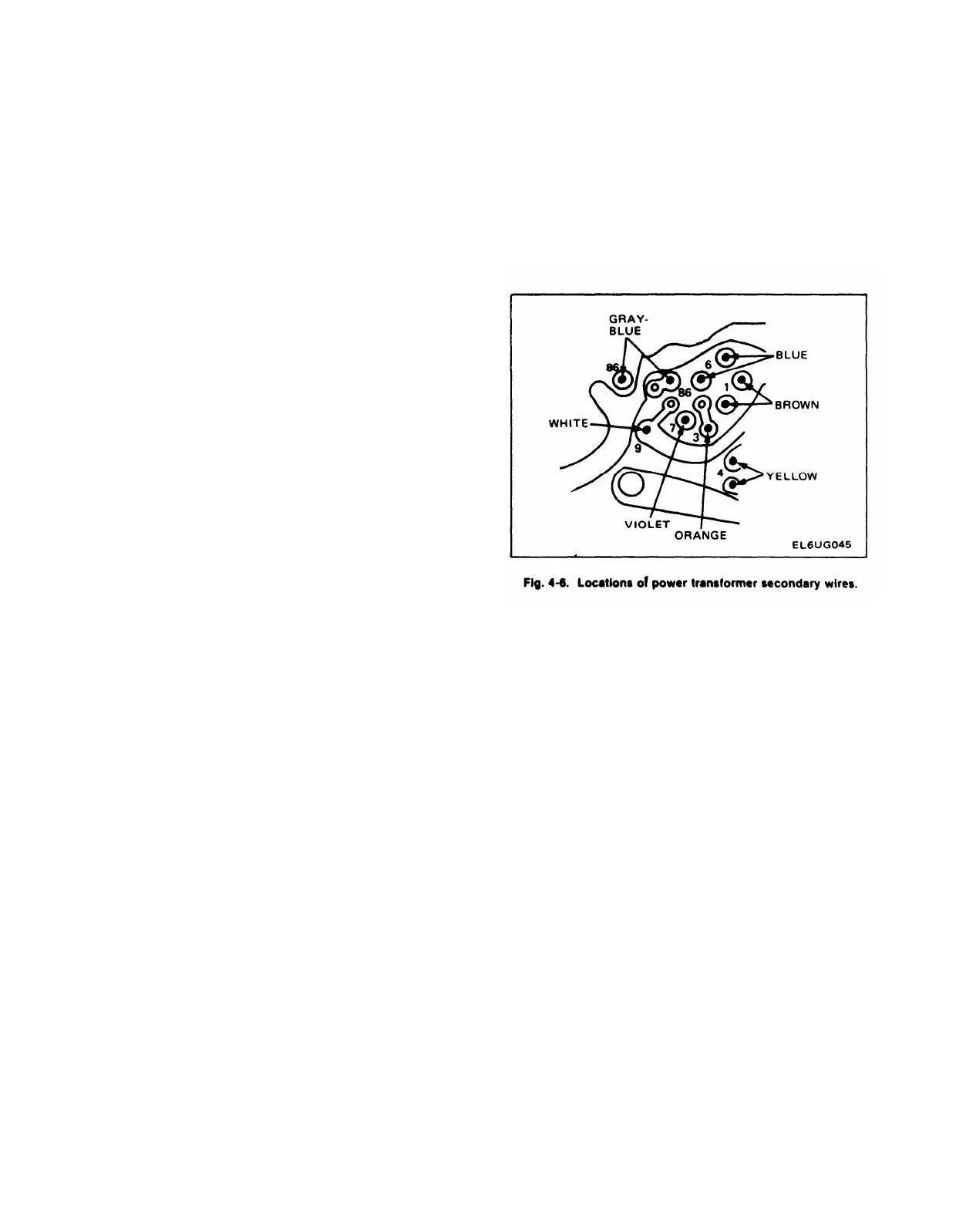
20. Unsolder the power-transformer wires from the
Main Interface board and confirm each wire color with its
location in Fig. 4-6. Record any exceptions to this
procedure to facilitate reassembly.
21. Remove the Main Interface circuit-board, using
care to prevent strain on any of the wires.
22. Remove the solder from the holes in the circuit-
board wire-terminal pads, where wires were removed in
this procedure, to facilitate installation.
To install the Main interface circuit-board, reverse the
removal procedure.
Power Transformer Removal
The Power Transformer can be removed as follows:
19. Separate the Main Interface circuit-board from the 1. Remove the Trigger Generator and Z-Axis logic
instrument chassis, using care to prevent damage to
circuit-board as outlined previously.
components and wiring. Carefully thread the interconnec-
ting cables through the board and chassis, as necessary,
to avoid strain on any cable. Let the board pivot on the
2. Remove the regulating-range selector cover and the
power-transformer leads still connected to the board.
blue rear-panel of the instrument.
4-29

 Loading...


