General Operating Instructions
3. These controls affect the right variable power supply. If the instrument is in
a tracking mode, the right power supply is the master. In a tracking mode,
either or both of the control knobs can affect both variable power supplies.
4.
These controls affect the left variable power supply. If the instrument is in a
tracking mode, the left power supply is the slave. In a tracking mode,
either or both of the control knobs have no effect.
5. These controls affect the fixed 5 V power supply.
The Variable Power Supplies
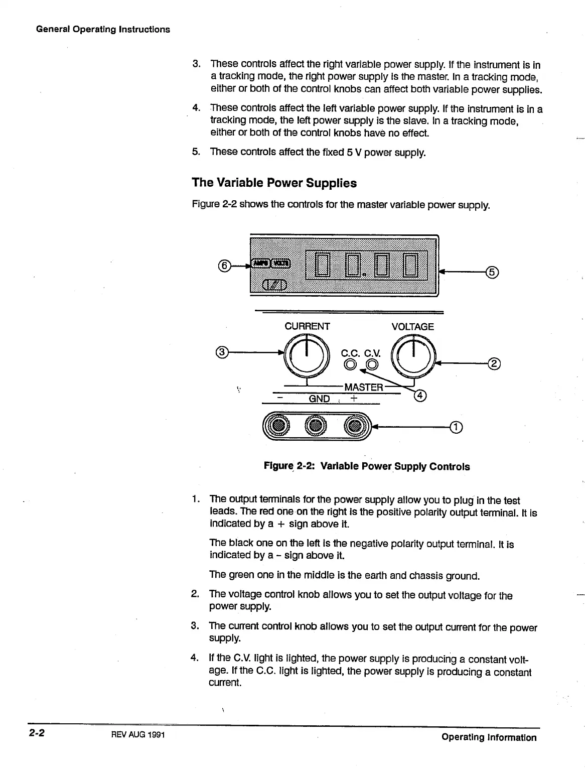
Figure 2-2 shows the controls for the master variable power supply.
CURRENT
VOLTAGE
Figure 2-2: Variable Power Supply Controls
1.
The output terminals for the power supply allow you to plug in the test
leads.
The red one on the right is the positive polarity output terminal. It is
indicated by a + sign above it.
The black one on the left is the negative polarity output terminal. It is
indicated by a - sign above it.
The green one in the middle is the earth and chassis ground.
2.
The voltage control knob allows you to set the output voltage for the
power supply.
3. The current control knob allows you to set the output current for the power
supply.
4.
If the C.V. light is lighted, the power supply is producing a constant volt-
age.
If the C.C. light is lighted, the power supply is producing a constant
current.
REV AUG
1991
Operating Information

 Loading...


