Removal and Installation Procedures
Power Transistor
Circuit Boards
Removal
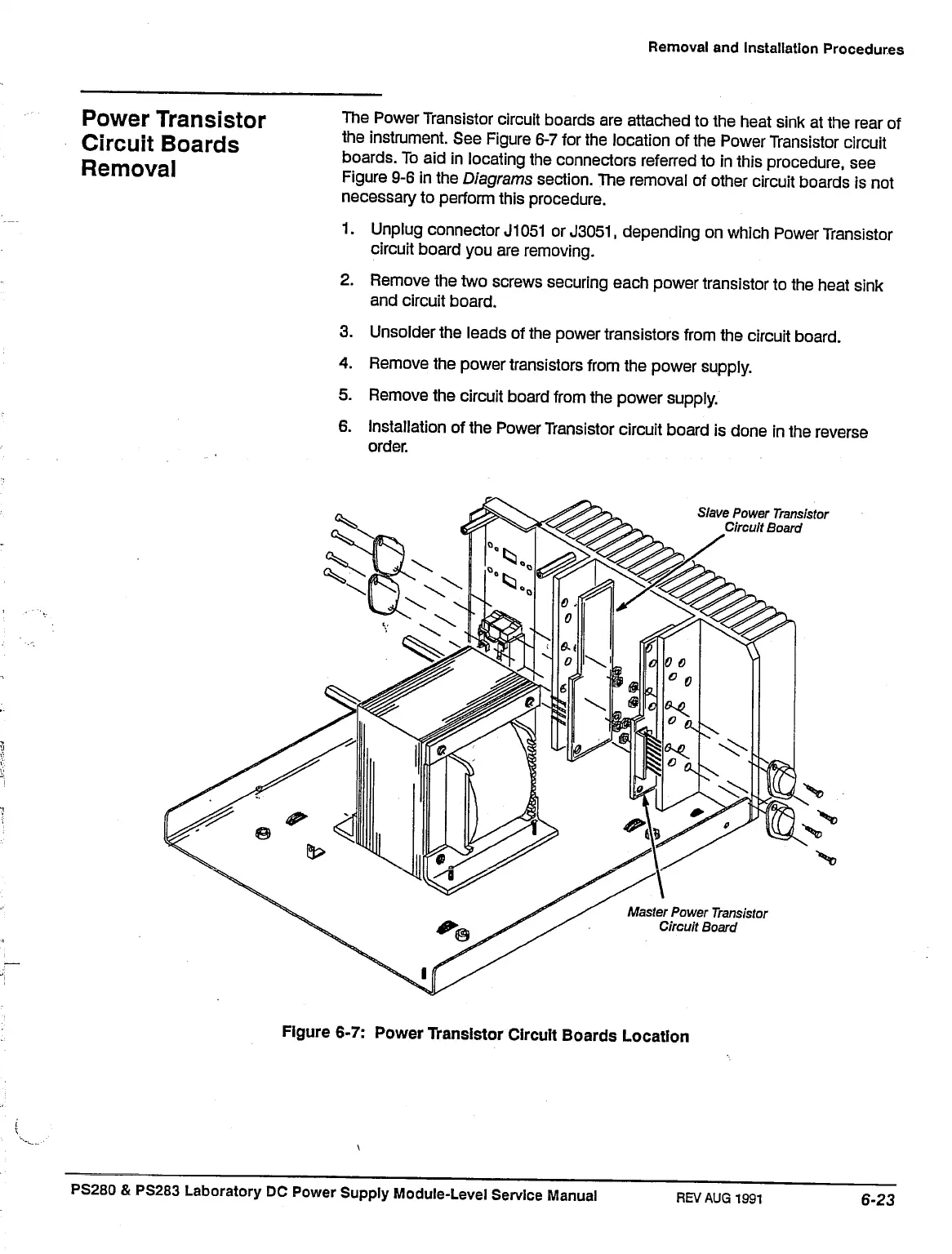
The Power Transistor circuit boards are attached to the heat sink at the rear of
the instrument. See Figure 6-7 for the location of the Power Transistor circuit
boards. To aid in locating the connectors referred to in this procedure, see
Figure 9-6 in the Diagrams section. The removal of other circuit boards is not
necessary to perform this procedure.
1.
Unplug connector
J1051
or
J3051,
depending on which Power Transistor
circuit board you are removing.
2.
Remove the two screws securing each power transistor to the heat sink
and circuit board.
3. Unsolder the leads of the power transistors from the circuit board.
4.
Remove the power transistors from the power supply.
5. Remove the circuit board from the power supply.
6. Installation of the Power Transistor circuit board is done in the reverse
Slave Power
Transistor
Circuit Board
Master Power
Transistor
Circuit Board
Figure 6-7: Power Transistor Circuit Boards Location
PS280
& PS283 Laboratory DC Power Supply Module-Level Service Manual
REV AUG
1991

 Loading...


