Performance Tests
f.
Verify
the voltage output range:
• Check that the Laboratory DC Power Supply can be adjusted from
0 to 30 V.
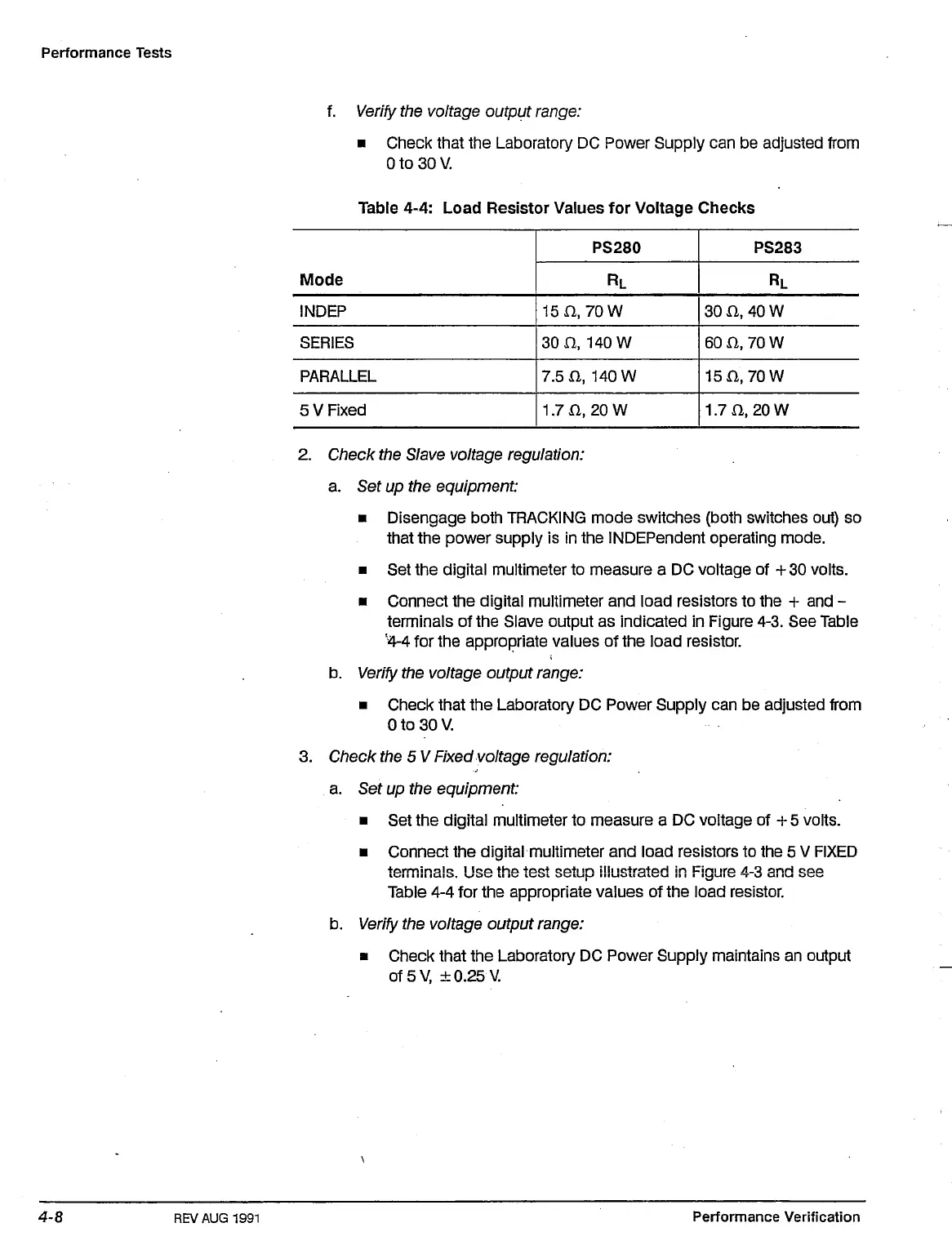
Table 4-4: Load Resistor Values for Voltage Checks
INDEP
SERIES
PARALLEL
5 V Fixed
15 n,
30
a
7.5 n,
1.7 n,
PS280
RL
70 W
140 W
140 W
20 W
PS283
RL
30 n, 40 W
60 a, 70 W
15n, 70W
1.7 n, 20 W
2. Check the Slave voltage regulation:
a. Set up the equipment:
• Disengage both TRACKING mode switches (both switches out) so
that the power supply is in the INDEPendent operating mode.
• Set the digital multimeter to measure a DC voltage of +
30
volts.
• Connect the digital multimeter and load resistors to the + and -
terminals of the Slave output as indicated in Figure 4-3. See Table
•4-4
for the appropriate values of the load resistor.
b.
Verify
the voltage output range:
• Check that the Laboratory DC Power Supply can be adjusted from
0 to 30 V.
3. Check the 5
V
Fixed voltage regulation:
a. Set up the equipment:
• Set the digital multimeter to measure a DC voltage of +5 volts.
• Connect the digital multimeter and load resistors to the 5 V FIXED
terminals. Use the test setup illustrated in Figure 4-3 and see
Table 4-4 for the appropriate values of the load resistor.
b.
Verify
the voltage output range:
• Check that the Laboratory DC Power Supply maintains an output
of5V, ± 0.25 V.
REVAUG 1991
Performance Verification

 Loading...


