Performance Tests
b.
Verify
the current regulation:
• Check that the output current level changes less than 0.2%
±3 mA while switching load resistor
RL1
in and out of the circuit
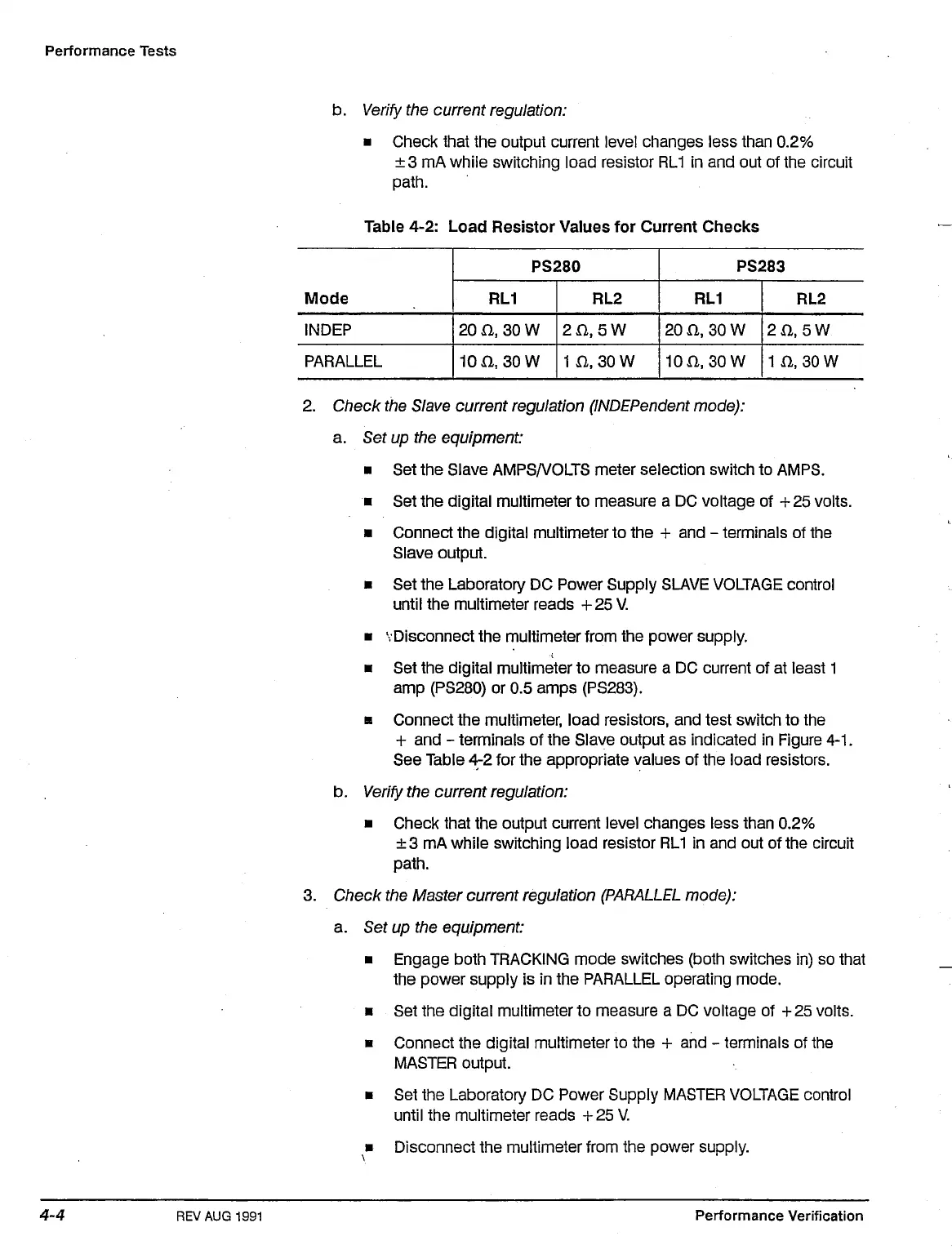
Table 4-2: Load Resistor Values for Current Checks
M
oae
INDEP
PARALLEL
RL1
20
D.,
30
10 a, 30
PS280
W
w
2O
in
RL2
,5W
,30W
20
10
RL1
a 30
a
so
PS283
W
w
RL2
2fl.5W
1
a
30
w
2.
Check the Slave current regulation
(INDEPendent
mode):
a. Set up the equipment:
• Set the Slave AMPS/VOLTS meter selection switch to AMPS.
• Set the digital multimeter to measure a DC voltage of + 25 volts.
• Connect the digital multimeter to the + and - terminals of the
Slave output.
• Set the Laboratory DC Power Supply SLAVE VOLTAGE control
until the multimeter reads +25 V.
• 'Disconnect the multimeter from the power supply.
• Set the digital multimeter to measure a DC current of at least 1
amp (PS280) or 0.5 amps (PS283).
a Connect the multimeter, load resistors, and test switch to the
+ and - terminals of the Slave output as indicated in Figure
4-1.
See Table 4^2 for the appropriate values of the load resistors.
b.
Verify
the current regulation:
• Check that the output current level changes less than 0.2%
±3 mA while switching load resistor
RL1
in and out of the circuit
3. Check the Master current regulation
(PARALLEL
mode):
a. Set up the equipment:
• Engage both TRACKING mode switches (both switches in) so that
the power supply is in the PARALLEL operating mode.
• Set the digital multimeter to measure a DC voltage of +
25
volts.
• Connect the digital multimeter to the + and - terminals of the
MASTER output.
• Set the Laboratory DC Power Supply MASTER VOLTAGE control
until the multimeter reads +25 V.
• Disconnect the multimeter from the power supply.
REV AUG
1991
Performance Verification

 Loading...


