General Operating Instructions
Rear Panel
Figure
2-4
shows the rear panel
of
the instrument.
•gggss
A©
^
1
^
S
s
TEOTRONKINC,
BEAVEHTON.,OH,U.SA
1UKXTAIWAMJI.0.C
y
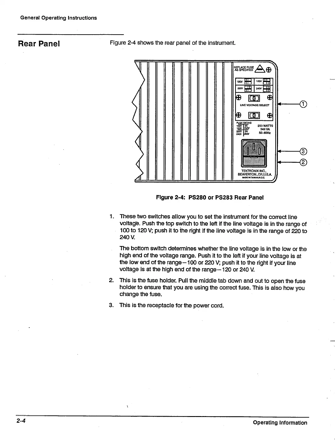
Figure 2-4: PS280
or
PS283 Rear Panel
1.
These two switches allow you
to
set the instrument for the correct line
voltage. Push the top switch
to
the left
if
the line voltage
is in
the range
of
100
to
120
V;
push
it to
the right
If
the line voltage
is in
the range
of
220
to
The bottom switch determines whether the line voltage
is
In the low or the
high end
of
the voltage range. Push
it to
the left
if
your line voltage
is at
the low end
of
the range-100
or
220
V;
push
it to
the right
if
your line
voltage
is at
the high end
of
the
range
-120
or
240 V.
2.
This
is
the fuse holder. Pull the middle tab down and out
to
open the fuse
holder to ensure that you are using the correct fuse. This
is
also how you
change the fuse.
3. This
is
the receptacle for the power
cord.
Operating Information

 Loading...


