Theory of Operation
5 V Fixed Voltage Output
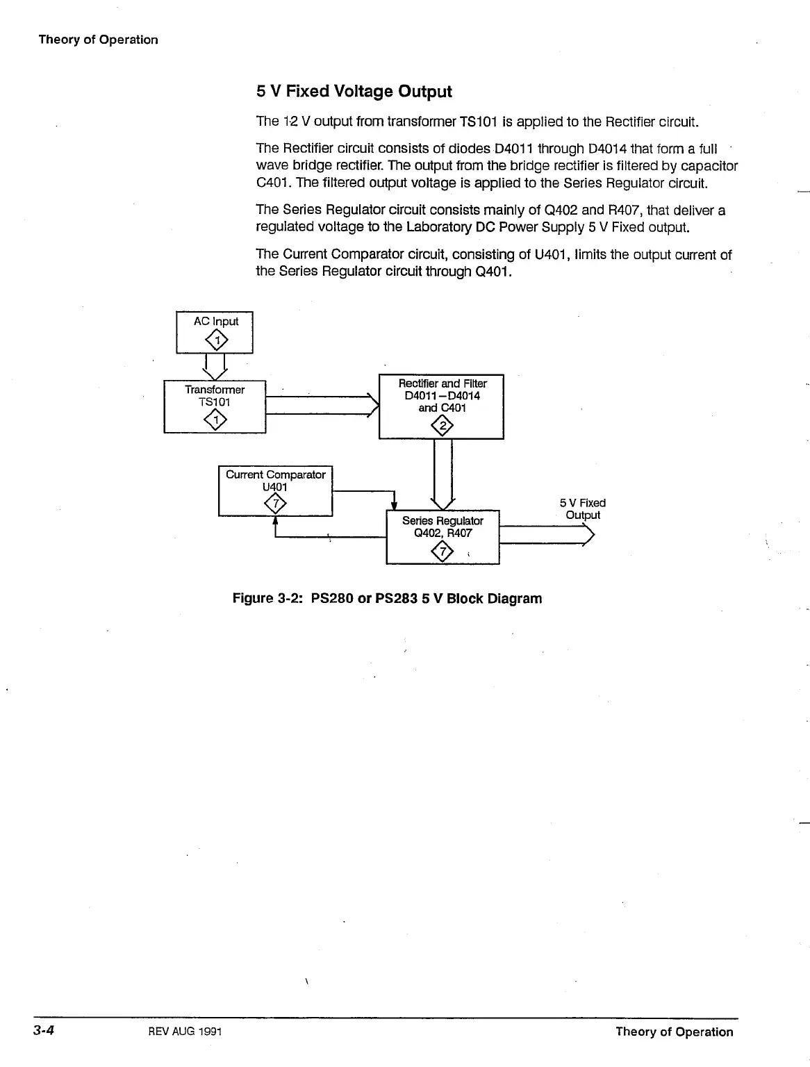
The 12 V output from transformer
TS101
is applied to the Rectifier circuit.
The Rectifier circuit consists of diodes D4011 through D4014 that form a full
wave bridge rectifier. The output from the bridge rectifier is filtered by capacitor
C401.
The filtered output voltage is applied to the Series Regulator circuit.
The Series Regulator circuit consists mainly of Q402 and R407, that deliver a
regulated voltage to the Laboratory DC Power Supply 5 V Fixed output.
The Current Comparator circuit, consisting of
U401,
limits the output current of
the Series Regulator circuit through Q401.
AC Input
u\
•
Transformer
Current Comparator
<>
Rectifier and Filter
D4011-D4014
andC401
Series Regulator
Q402,
R407
<2>
5 V Fixed
Output
>
Figure 3-2: PS280 or PS283 5 V Block Diagram
REVAUG 1991
Theory of Operation

 Loading...


