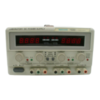
Adjustment Procedures
• Connect the digital multimeter to the + and - terminals of the
Slave output.
b. Make the zero volts adjustment:
• Adjust VR302 for a reading of-15 mV, within ± 15 mV on the
multimeter.
c. Set up the equipment:
• Set the digital multimeter to measure a DC voltage of ± 35 V.
• Set the SLAVE VOLTAGE control to maximum (fully clockwise).
d.
Make the maximum volts adjustments:
• Adjust
VR301
for a reading of 31.5 V on the multimeter.
• Adjust
VR601
until the Laboratory DC Power Supply meter dis-
plays 31.5V.
3. Adjust the master current output:
a. Set up the equipment:
• Disengage both TRACKING mode switches (both switches out) so
that the power supply is in the INDEPendent operating mode.
• Set the Master AMPS/VOLTS meter selection switch to AMPS.
• Set the digital multimeter to measure a DC current of 2 A.
•, Connect the digital multimeter to the + and - terminals of the
Master output. .
• Set the MASTER CURRENT control to maximum (fully clockwise).
b. Make the current adjustments:
• Adjust VR103 for a reading of 1.05 A (PS283) or
2.1
A (PS280) on
the multimeter.
• Adjust VR202 until the Laboratory DC Power Supply meter dis-
plays 1.05 A (PS283) or
2.1
A (PS280).
4.
Adjust the slave current output:
a. Set up the equipment:
• Disengage both TRACKING mode switches (both switches out) so
that the power supply is in the INDEPendent operating mode.
• Set the Slave AMPS/VOLTS meter selection switch to AMPS.
• Set the digital multimeter to measure a DC current of 2 A.
• Connect the digital multimeter to the + and - terminals of the
Slave output.
• Set the SLAVE CURRENT control to maximum (fully clockwise).
5-4
REV AUG1991
Adjustment

 Loading...