General Operating Instructions
5. The LED display lights when the instrument is turned on. The numbers
indicate the voltage or current produced by the variable power supply.
6. The AMPS/VOLTS meter selection switch determines whether the LED
display shows the current or the voltage. If the switch is pushed to the left,
the display shows the current. If the switch is pushed to the right, the
display shows the voltage.
The meter selection switch is to the right of the corresponding display for the
slave variable power supply. All other controls are the same for both variable
power supplies.
The Fixed Voltage Power Supply
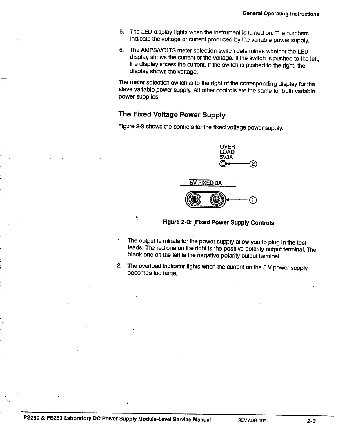
Figure 2-3 shows the controls for the fixed voltage power supply.
5V FIXED 3A
Figure 2-3: Fixed Power Supply Controls
1.
The output terminals for the power supply allow you to plug in the test
leads.
The red one on the right is the positive polarity output terminal. The
black one on the left is the negative polarity output terminal.
2.
The overload indicator lights when the current on the 5 V power supply
becomes too large.
PS280 & PS2S3 Laboratory DC Power Supply Module-Level Service Manual
REV
AUG 1991
2-3

 Loading...


