Theory of Operation
The Reference Voltage Amplifier circuit consists mainly of U103, and the
Voltage Comparator circuit consists mainly of U104. U104 compares the
voltage from the Reference Voltage Amplifier with feedback from the output
voltage and, through diode D105 and the amplifier circuit of Q103 and Q104,
provides a calibrated output voltage.
The Tracking Selector switches (S501A and S501B), along with the Tracking
Delay circuit (U501 and U502), Relay Control circuit
(Q501,
Q502, and Q503),
and the Tracking Relays
(RL501,
RL502, and RL503) set the configuration of
the Master and Slave outputs.
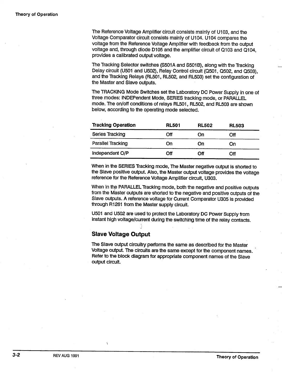
The TRACKING Mode Switches set the Laboratory DC Power Supply in one of
three modes: INDEPendent Mode, SERIES tracking mode, or PARALLEL
mode.
The on/off conditions of relays
RL501,
RL502, and RL503 are shown
below, according to the operating mode selected.
Tracking Operation
Series Tracking
Parallel Tracking
Independent O/P
Off
On
Off
On
On
Off
Off
On
Off
When in the SERIES Tracking mode, The Master negative output is shorted to
the Slave positive output. Also, the Master output voltage provides the voltage
reference for the Reference Voltage Amplifier circuit, U303.
When in the PARALLEL Tracking mode, both the negative and positive outputs
from the Master outputs are shorted to the negative and positive outputs of the
Slave outputs. A reference voltage for Current Comparator U305 is provided
through R1261 from the Master supply circuit.
U501 and U502 are used to protect the Laboratory DC Power Supply from
instant high voltage/current during the switching time of the relay contacts.
Slave Voltage Output
The Slave output circuitry performs the same as described for the Master
Voltage output. The circuits are the same except for the component names.
Refer to the block diagram for appropriate component names of the Slave
output circuit.
3-2
REV
AUG1991
Theory of Operation

 Loading...


