Operating Basics
SPG600 & SPG300 Sync Pulse Generators User Manual 2-3
Reference Indicators
The reference indicators indicate whether the sync pulse generator is locked to its
internal oscillator or an external reference signal.
INT.REF. This indicator lights when the sync pulse generator is using its internal
reference oscillator.
EXT.REF. This indicator lights when the sync pulse generator is locked to an
external reference signal. A blinking indicator means that the sync pulse generator
is using the external reference signal but is unable to lock to the signal.
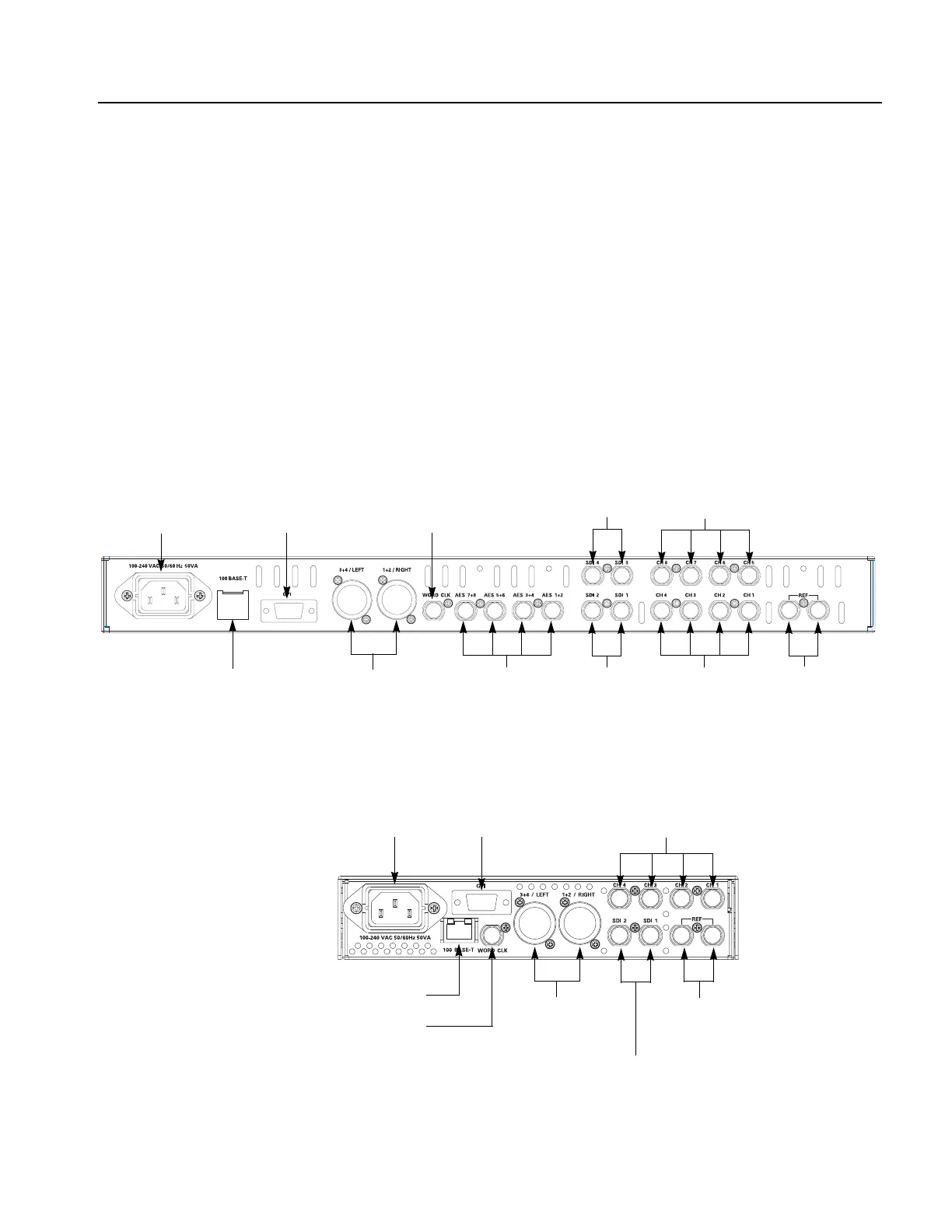
Rear-Panel Connectors
Figure 2-3 and 2-4 show the locations of the rear panel connectors of the SPG600
and SPG300. A brief discussion of each feature follows the illustration.
Figure 2-3: SPG600 rear panel (Option 0203)
Figure 2-4: SPG300 rear panel
Power connector
100 BASE-T
GPI
Analog outputs
Serial digital
outputs
REF connectors
AES/EBU Serial
digital audio outputs
Word clock output
AES/EBU serial digital
or analog audio outputs
(XLR connector)
Serial digital outputs
(Option 03)
Analog outputs
(Option 02)
REF connectors
Serial digital outputs
AES/EBU serial digital
or analog audio outputs
(XLR connector)
Analog outputs
GPI
100 BASE-T
Word clock output
Power connector
 Loading...


