Using the General Purpose Interface (GPI)
3-42 SPG600 & SPG300 Sync Pulse Generators User Manual
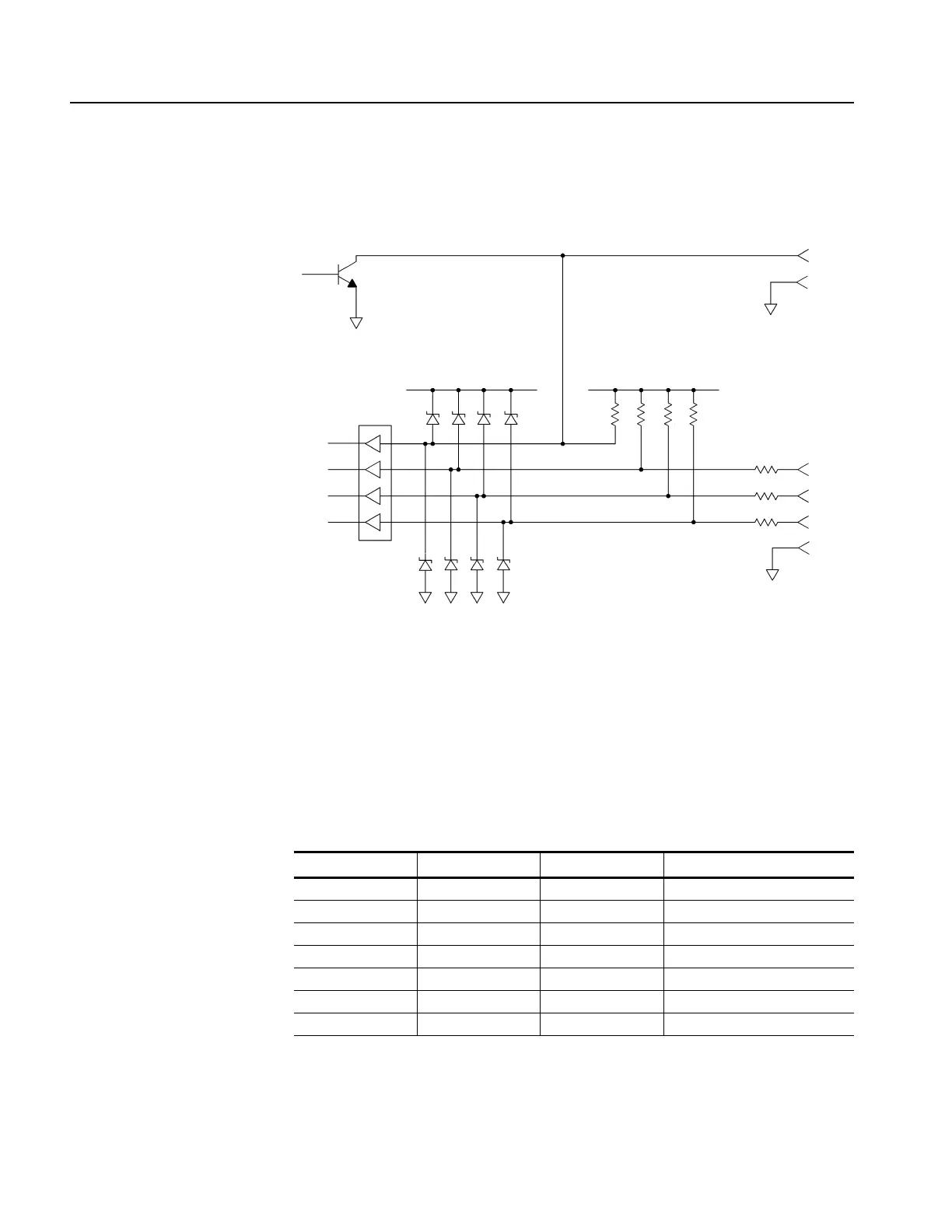
Figure 3-26 shows the input/output circuit of GPI.
Figure 3-26: Input/output circuit of GPI
Recalling a Preset
You can recall one of the seven presets by combinations of signal levels on pins 3,
4, and 5 of the GPI connector. Table 3-7 shows the combinations of signal levels
for the pins and the preset number to be recalled.
Output circuit
Input circuit
Pin 1
Pin 9
Pin 3
Pin 4
Pin 5
Pin 6
+5 V
+5 V
74LVTH244A
10 Ω
10 Ω
10 Ω
10 kΩ
10 kΩ
10 kΩ
10 kΩ
Table 3-7: Combinations of signal levels and the corresponding preset
Pin 3 Pin 4 Pin 5 Preset number
Low High High 1
High Low High 2
Low Low High 3
High High Low 4
Low High Low 5
High Low Low User Default
Low Low Low Factory Default
 Loading...


