Menus
SPG600 & SPG300 Sync Pulse Generators User Manual 3-9
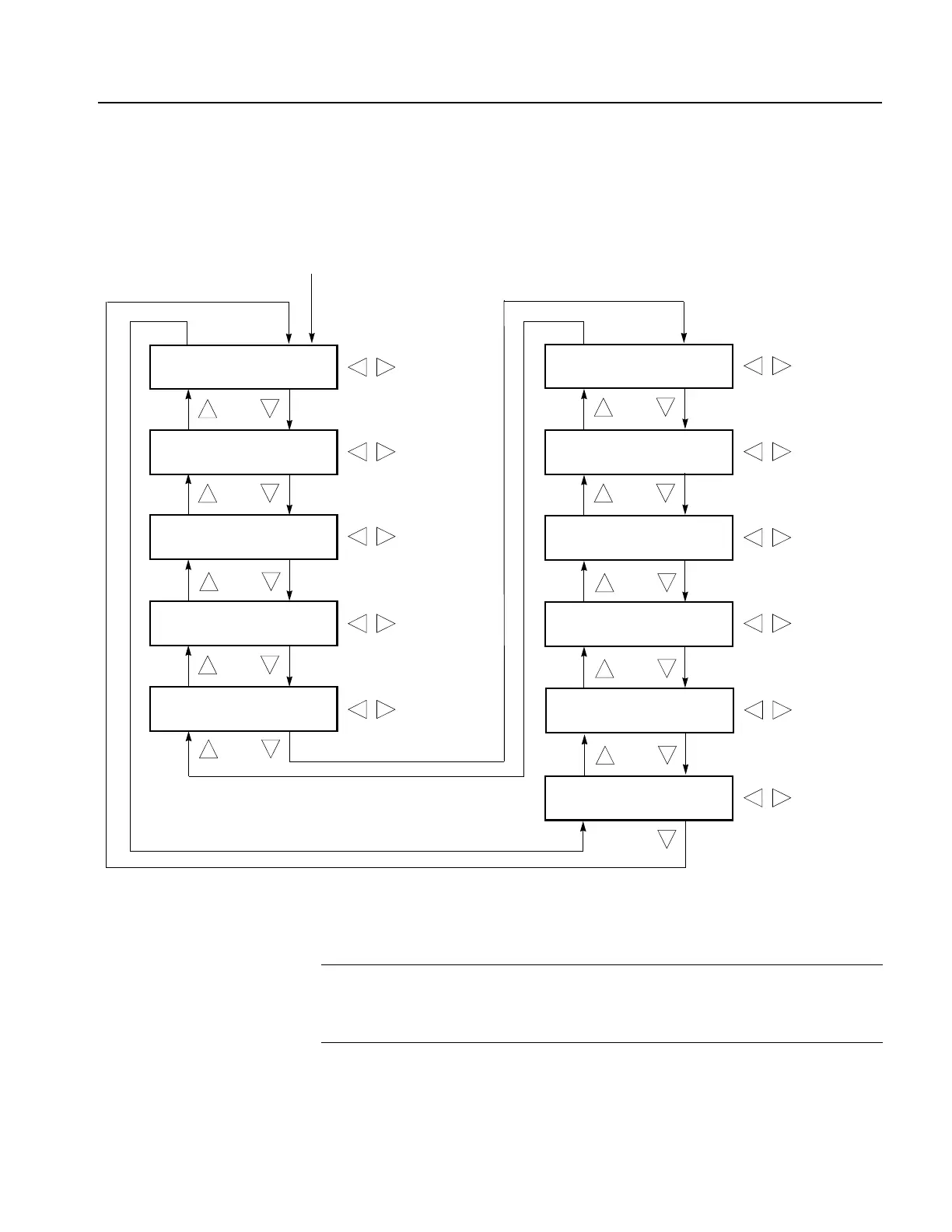
Test Signal (SDI) Submenu
This menu allows you to select a serial digital test signal for a SDI output(s). Use
the up (
S) or down (T) arrow button to scroll through the menu. Figure 3-4 shows
the Test signal (SDI) submenu diagram.
Figure 3-4: Test signal (SDI) submenu diagram
Select TEST SIGNAL (SDI) in the Video menu
Select a signal
TIMING
2.5 MHz Bowtie
REC 801
100% Color Bars
SDI
Checkfield
MULTI BURST
60% Y Multiburst
MONITOR
2 Pedestal & Pluge
LINEARITY
10 Step
FLAT FIELD
0 % Flat Field
COLOR BAR
SMPTE Color Bars
Select a signal
Select a signal
PULSE BAR
2T Pulse & Bar
Select a signal
Select a signal
Select a signal
Select a signal
Select a signal
Select a signal
SWEEP
100% Sweep
Select a signal
OTHER
Chroma Freq. Resp.
Select a signal
NOTE. By default, the sync pulse generator is configured to output a test signal
from the SDI 2 connector. You can change the configuration of the SDI outputs
using the Configuration submenu. Refer to the Configuration submenu on
page 3-37.
 Loading...


