EasyManua.ls Logo

Teldat Regesta Smart PRO User Manual

Teldat Regesta Smart PRO
48 pages
To Next Page IconTo Next Page
To Previous Page IconTo Previous Page
Page #18 background image
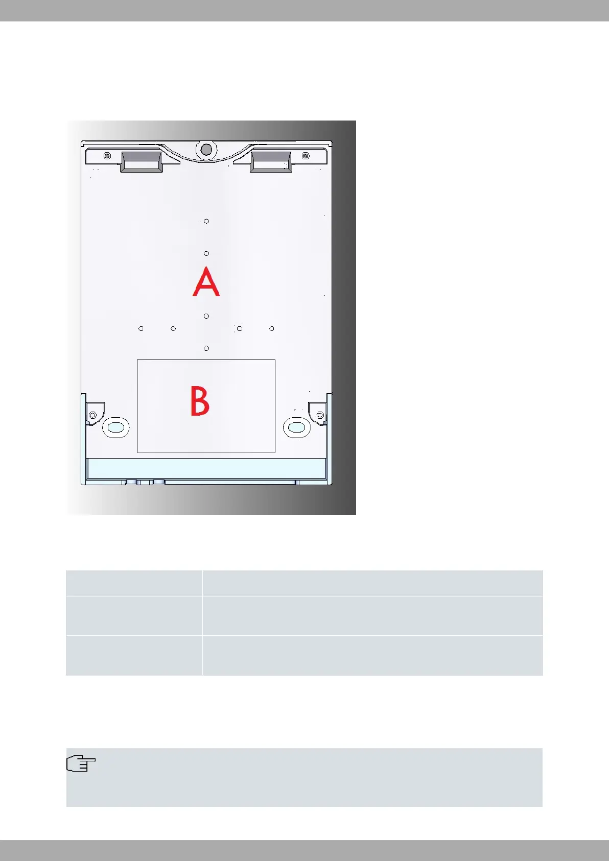
2.4.3 Underside panel
The underside panel features the router identification label and various perforations to accommodate different mount-
ing options. The following figure depicts the underside panel in detail:
Fig. 4: Underside Panel
The following elements can be found on the underside panel:
Underside Panel elements
Item Description
A Slots for the accessories to attach the device to a DIN rail mount. For further in-
formation on this accessory, please see section Wall mounting on page 18.
B The platform on which the product information label is affixed. This label contains
details such as the device model, MAC address, serial number, and more.
2.5 Power supply
The Regesta Smart PRO provides three distinct Power Supply options, depending on the specific model.
Note
Please ensure that you have identified your router model and carefully read the instructions before con-
necting the router!
Teldat S.A.
2 Product Overview
Regesta Smart PRO 13

Table of Contents

Questions and Answers:

Teldat Regesta Smart PRO Specifications

General IconGeneral
Connectivity TechnologyWired, Wireless
Frequency Band2.4 GHz, 5 GHz
Security ProtocolsWPA, WPA2, WPA3
TypeRouter
WAN1 x 10/100/1000 Mbps
LAN4 x 10/100/1000 Mbps
Wi-Fi802.11a/b/g/n/ac
Cellular4G LTE
Power Supply12V DC
Device TypeRouter
Wireless StandardsIEEE 802.11a/b/g/n/ac
FirewallStateful Packet Inspection (SPI)
Management InterfaceCLI

Summary

Safety warnings

Technical support

Device models

Hardware features

Components

Front panel

Details the front panel, including status LEDs and their meanings.

Connector panel

Power supply

Installing the Router

Workplace conditions

Important conditions for installing the equipment safely and correctly.

Removing/Installing the connector protector

Step-by-step guide to remove and install the connector protective casing.

Installing a DIN rail mount

Wall mounting

Connecting the Router

Power source

Details on how to connect the router to a power source.

Power connector pins

Explains the power connector and its pins for DC and AC power.

Data connections

Overview of various data connection types available on the router.

LAN connection

Details the Gigabit Ethernet LAN port and its specifications.

WAN connections

Describes the WAN interface, including SFP and RJ-45 connectors.

WWAN antenna connections (RF connectors)

Information on connecting WWAN antennas for cellular connectivity.

Serial port connections

Overview of serial port connections available on the router.

Troubleshooting

Provides solutions for common installation and operational issues.

LAN switch connector

WWAN/RF connectors

Configuration connector

RS-232 serial port connectors

RS-485 serial port connectors

Power supply connector

Technical specifications

LAN interface

WAN Base-T interface

Switch interface

WAN SFP interface

Wireless WAN interface

Configuration interface

RS-232 serial interface

RS-485 serial interface

Power supply specifications