www.ti.com
EVM Overview
5
SBAU090E–November 2003–Revised November 2018
Submit Documentation Feedback
Copyright © 2003–2018, Texas Instruments Incorporated
ADS1256EVM and ADS1256EVM-PDK
1.2 Introduction
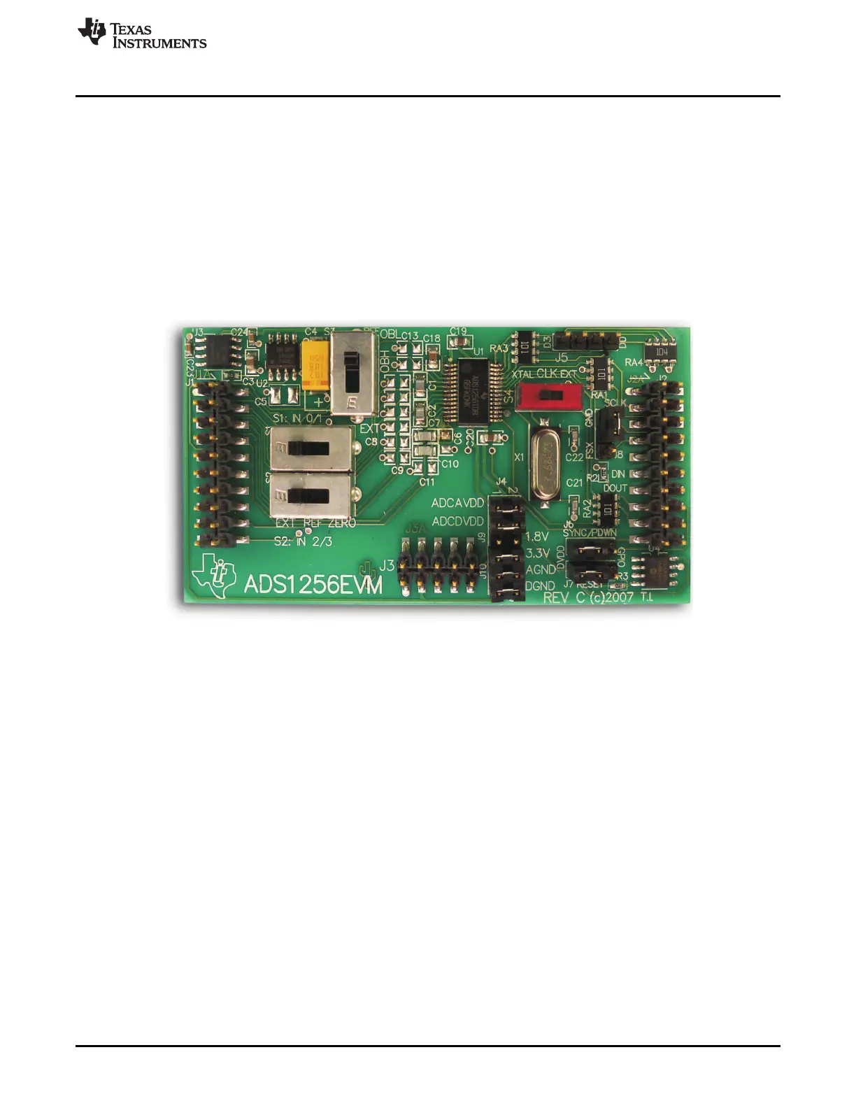
The ADS1256EVM, shown in Figure 1, is an evaluation module built to the TI Modular EVM System
specification. It can be connected to any Modular EVM System interface card.
The ADS1256EVM is available as a stand-alone printed circuit board (PCB) or as part of the
ADS1256EVM-PDK, which includes an MMB0 motherboard and software. As a stand-alone PCB, the
ADS1256EVM is useful for prototyping designs and firmware.
Note that the ADS1256EVM has no microprocessor and cannot run software. To connect it to a computer,
some type of interface is required.
If you intend to use the ADS1255 in your application, use the ADS1256EVM for evaluation and test
purposes. The ADS1255 is in a smaller package, and lacks inputs AIN2 through AIN7; otherwise, it is
identical to the ADS1256.
Figure 1. ADS1256EVM
1.3 Built-In Accessories
The ADS1256EVM includes a system clock crystal and a low-noise voltage reference. Both are optional;
you can select an external system clock and an external reference using slide switches.
The +2.5V reference circuit is based on a REF5025 buffered by an OPA350 and filtered by a large
tantalum electrolytic capacitor. While its noise performance is not sufficiently low to allow the ADS1256 to
perform at its lowest noise level at all data rates, the circuit can closely approach this limit, and is
representative of the kind of reference circuit used in many applications.
1.4 Connectors
The ADS1256 device on the ADS1256EVM is connected through four headers: the analog connector, the
serial connector, the power connector, and the GPIO header. This section describes the respective
pinouts and locations for the connectors and header.
The analog connector (J1) carries analog I/O. The ADS1256 has a nine-input multiplexer connected
through pins 1 through 8 and 10. An optional external differential reference can be connected to pins 18
and 20.
The serial connector (J2) carries the ADS1256 serial digital interface, an optional external system clock
signal, and an I
2
C™ connection to the onboard serial EEPROM.

 Loading...


