www.ti.com
Evaluation Board Inputs and Outputs
17
SNAU145B–MAY 2013–Revised March 2018
Submit Documentation Feedback
Copyright © 2013–2018, Texas Instruments Incorporated
LMK04826 and LMK04828 User’s Guide
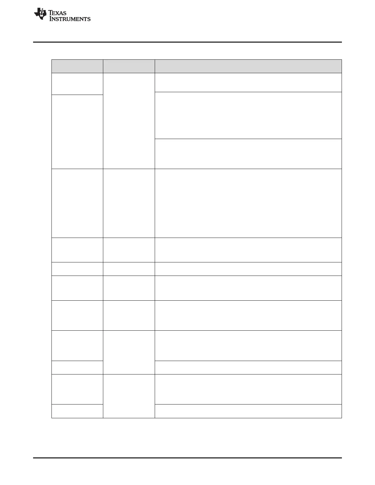
Table 5. Description of Evaluation Board Inputs and Outputs (continued)
CONNECTOR NAME
SIGNAL TYPE,
INPUT/OUTPUT
DESCRIPTION
Populated:
CLKin0, CLKin0*,
CLKin1*
Analog,
Input
Reference Clock Inputs for PLL1 (CLKin0, 1). CLKin1 can alternatively be used as
an External Feedback Clock Input (FBCLKin) in 0-delay mode or an RF Input (Fin)
in External VCO mode.
Reference Clock Inputs for PLL1 (CLKin0, 1)
FBCLKin/CLKin1* is configured by default for a single-ended reference clock input
from a 50-ohm source. The non-driven input pin (FBCLKin/CLKin1) is connected to
GND with a 0.1 µF. CLKin0/CLKin0* is configured by default for a differential
reference clock input from a 50-ohm source.
CLKin1* is the default reference clock input selected in TICS Pro. The clock input
selection mode can be programmed on the Set Modes page through the
LMK0482x Sub-Modes.
Not Populated:
CLKin1
External Feedback Input (FBCLKin) for 0-Delay
CLKin1 is shared for use with FBCLKin as an external feedback clock input to PLL1
for 0-delay mode. See the LMK04820 family datasheet (literature number
SNAS605) for more details on using 0-delay mode with the evaluation board and
the evaluation board software.
Populated:
OSCin, OSCin*
Analog,
Input
Feedback VCXO clock input to PLL1 and Reference clock input to PLL2.
The single-ended output of the onboard VCXO (U4) drives the OSCin* input of the
device and the OSCin input of the device is connected to GND with 0.1 µF.
A VCXO add-on board may be optionally attached through these SMA connectors
with minor modification to the components going to the OSCin/OSCin* pins of
device. This is useful if the VCXO footprint does not accommodate the desired
VCXO device or if the user desires to use the LMK0482xB in single loop mode.
A single-ended or differential signal may be used to drive the OSCin/OSCin* pins
and must be AC coupled. If operated in single-ended mode, the unused input must
be connected to GND with 0.1 µF.
Refer to the LMK04820 family datasheet section “Electrical Characteristics” for
PLL2 Reference Input (OSCin) specifications (literature number SNAS605).
Test point:
VTUNE1_TP
Analog,
Input
Tuning voltage output from the loop filter for PLL1.
If a VCXO add-on board is used, this tuning voltage can be connected to the
voltage control pin of the external VCXO when this SMA connector is installed and
connected through R72 by the user.
Test point:
VTUNE2_TP
Analog,
Input
Tuning voltage output from the loop filter for PLL2.
Test points:
SDIO
SCK
CS*
CMOS,
Input/Output 10-pin header for SPI programming interface and programmable logic I/O pins for
the LMK0482x.
Populated:
SPI
10-pin header for SPI programming interface and programmable logic I/O pins for
the LMK0482x.
The programmable logic I/O signals accessible through this header include:
RESET, SYNC, Status_LD1, Status_LD2, CLKin_SEL0, and CLKin_SEL1. These
logic I/O signals also have dedicated SMAs and test points.
Test point:
Status_LD1_TP
CMOS,
Input/Output
Programmable status output pin. By default, set to output the digital lock detect
status signal for PLL1.
In the default TICS Pro modes, LED D5 will illuminate green when PLL1 lock is
detected by the LMK0482x (output is high) and turn off when lock is lost (output is
low).
Status_LD
The status output signal for the Status_LD1 pin can be selected on the User
Controls page through the PLL1_LD_MUX control.
Test point:
Status_LD2_TP
CMOS,
Input/Output
Programmable status output pin. By default, set to output the digital lock detect
status signal for PLL2.
In the default TICS Pro modes, LED D4 will illuminate green when PLL1 lock is
detected by the LMK0482x (output is high) and turn off when lock is lost (output is
low).
Status_LD2
The status output signal for the Status_LD1 pin can be selected on the User
Controls page through the PLL2_LD_MUX control.
 Loading...


