6.Installthebatteryontothemachineandconnectthe
batterycables;refertoInstallingtheBattery(page40).
Note:Donotrunthemachinewiththebattery
disconnected;electricaldamagemayoccur.
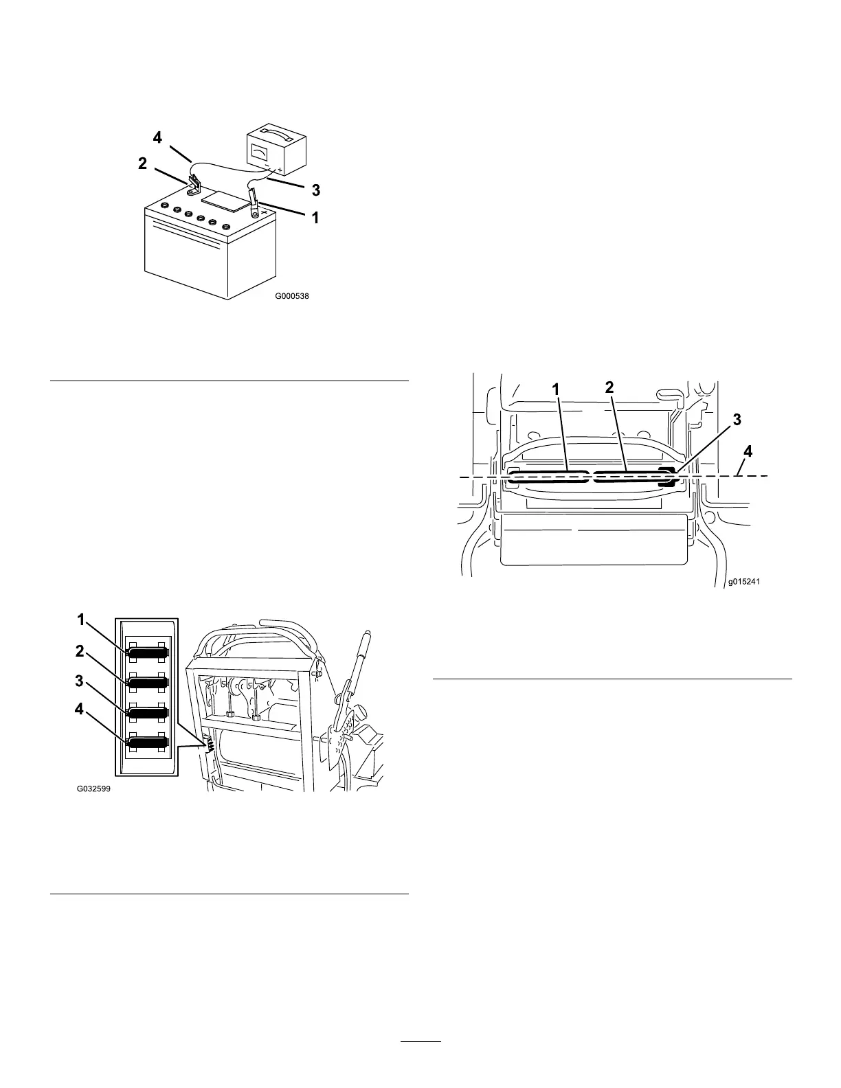
Figure53
1.Positivebatterypost
3.Red(+)chargerlead
2.Negativebatterypost
4.Black(-)chargerlead
ServicingtheFuses
Theelectricalsystemisprotectedbyfuses.Itrequiresno
maintenance.Ifafuseblows,checkthecomponentorcircuit
foramalfunctionorshort.
1.Releasetheoperatorcushionfromtherearofthe
machine.
2.Pulloutonthefusetoremoveandreplaceit(Figure
54).
3.Installtheoperatorcushion.
Figure54
1.Optionalaccessory
fuse—15A
3.Chargefuse—25A
2.Power-takeoff(PTO)
fuse—10A
4.Mainfuse—30A
DriveSystem
Maintenance
AdjustingtheTracking
Note:Determinetheleftandrightsidesofthemachine
fromthenormaloperatingposition.
1.Pushbothcontrolleversforwardthesamedistance.
2.Checkifthemachinepullstooneside.
Note:Ifitdoes,stopthemachineandsettheparking
brake.
3.Releasethecushionfromtherearofthemachine.
4.Rotatetherightcableadjustmenttopositiontheright
motion-controlleverinthecenterofthecontrol-panel
neutral-lockslot(Figure56).
Figure55
1.Leftmotion-controllever
3.Neutral-lockposition
2.Rightmotion-controllever4.Alignthecontrollevers
fronttoback.
5.Rotatetheleftcableadjustmenttomatchtheleftwheel
speedtothepreviouslysetrightwheelspeed.
6.Adjustinquarter-turnincrementsuntilthemachine
tracksstraight.
Note:Onlyadjusttheleftcabletomatchthe
leftwheelspeedtotherightwheelspeed.Donot
adjusttherightwheelspeedasthispositionsthe
rightmotion-controlleveroutofthecenterforthe
control-panelneutral-lockslot.
41

 Loading...