ENGINE
4-5
Toro TimeCutter SW/SWX Service Manual
4
Engine Installation
1. Position the engine onto the frame.
2. Connect the battery ground wires (B) to the engine
block, and connect the positive battery wire to the
engine starter motor.
3. Connect the chassis to engine harness connector
(A).
4. Install the fuel and vent lines to the engine.
5. Install the throttle and choke cables to carburetor
linkage.
6. Apply Loctite
®
242 to the (4) engine mounting bolts.
7. By hand, install the (4) engine mounting bolts.
Note: One of the engine mounting bolts also
secures the clutch stop to the frame. See the
exploded views on the following page for
application and mounting location.
8. In a cross pattern, torque the (4) engine mounting
boltstospecication-33ft-lbs.(44Nm).
9. Installmuferandnewmufergaskets,ifnecessary,
totheengineandtorquemuferfastenersto
specication-13ft-lbs.(17.5Nm)
10. Installheatshieldtothemuferandtorquefasteners
tospecication-5ft-lbs.(7Nm)
11. Apply anti-seize to the engine crankshaft and the
ends of the drive pulley shaft.
12. Install drive pulley onto the crankshaft and install
drive belt.
13. Install clutch washer onto the PTO clutch bolt. Apply
Loctite 242 to the PTO clutch bolt threads.
14. Install the PTO clutch onto crankshaft. Be sure PTO
clutch engages with the clutch stop bracket.
15. InstallandtorquethePTOclutchbolttospecication
– 55 ft-lbs. (76 Nm).
16. Install PTO belt onto PTO clutch. Verify proper PTO
belt routing as shown on pages 6-6 - 6-8.
17. Connect battery cables and verify engine oil level.
18. Safely start engine and verify proper operation.
Fig. 038 PICT-1084
14. The engine can now be lifted vertically from the
frame.
Engine Removal
1. Raise seat and disconnect battery terminals.
2. Disconnect wire harness connection to PTO clutch.
3. Remove PTO belt.
4. Remove PTO clutch bolt.
5. Remove drive belt and drive pulley from crankshaft.
6. If necessary, remove rear engine guard.
7. Remove the (2) fasteners that secure the heat shield
tothemuferandremovetheheatshield.Ifneces-
sary,removethemuferfromtheengine.
8. Remove the (4) engine to frame mounting bolts.
Make note of clutch stop bracket mounting
orientation.
9. Safely disconnect the fuel and vent lines from
engine.
10. Remove the throttle and choke cable from carburetor
linkage.
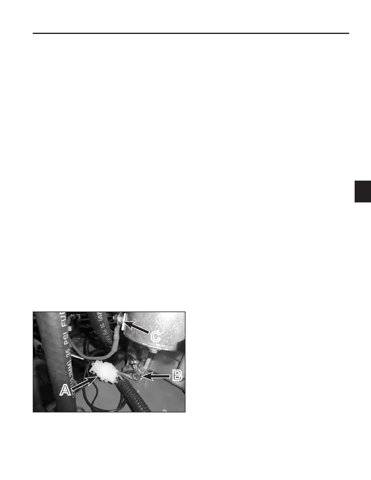
11. Disconnect chassis from engine electrical
connection (A) (Fig. 038).
12. Disconnect the ground wires from the engine block
(B) (Fig. 038).
13. Disconnect the positive battery cable (C) from the
starter motor (Fig. 038).
A
C
B
 Loading...