112
6-8-3. Snowfall Fan Control
Operation
An external snowfall signal turns on the outdoor unit fan.
The input signal is recognized during its rising/falling phase.
(After reaching the top/bottom of the rising/falling edge, the signal must remain there for at least 100 ms.)
The optional P.C. board should be connected to the header outdoor unit (U1).
6-8-4. External master ON/OFF Control
Operation
The system is started/stopped from the outdoor unit.
The input signal is recognized during its falling phase. (After reaching the bottom of the falling edge, the signal must
remain there for at least 100 ms.)
CAUTION
(1) Do not turn on the COOL (SW1) and HEAT (SW2) terminals simultaneously.
(2) Be sure to provide a contact for each terminal.
External signal: No-voltage pulse contact
The optional P.C. board should be connected to the header outdoor unit (U1).
Terminal Input signal Operation
COOL
(SW1)
Snowfall fan control
(Turns on outdoor
unit fan)
Normal operation
(Cancels control)
Terminal Input signal Operation
COOL
(SW1)
Turns on all indoor
units
HEAT
(SW2)
Turns off all indoor
units
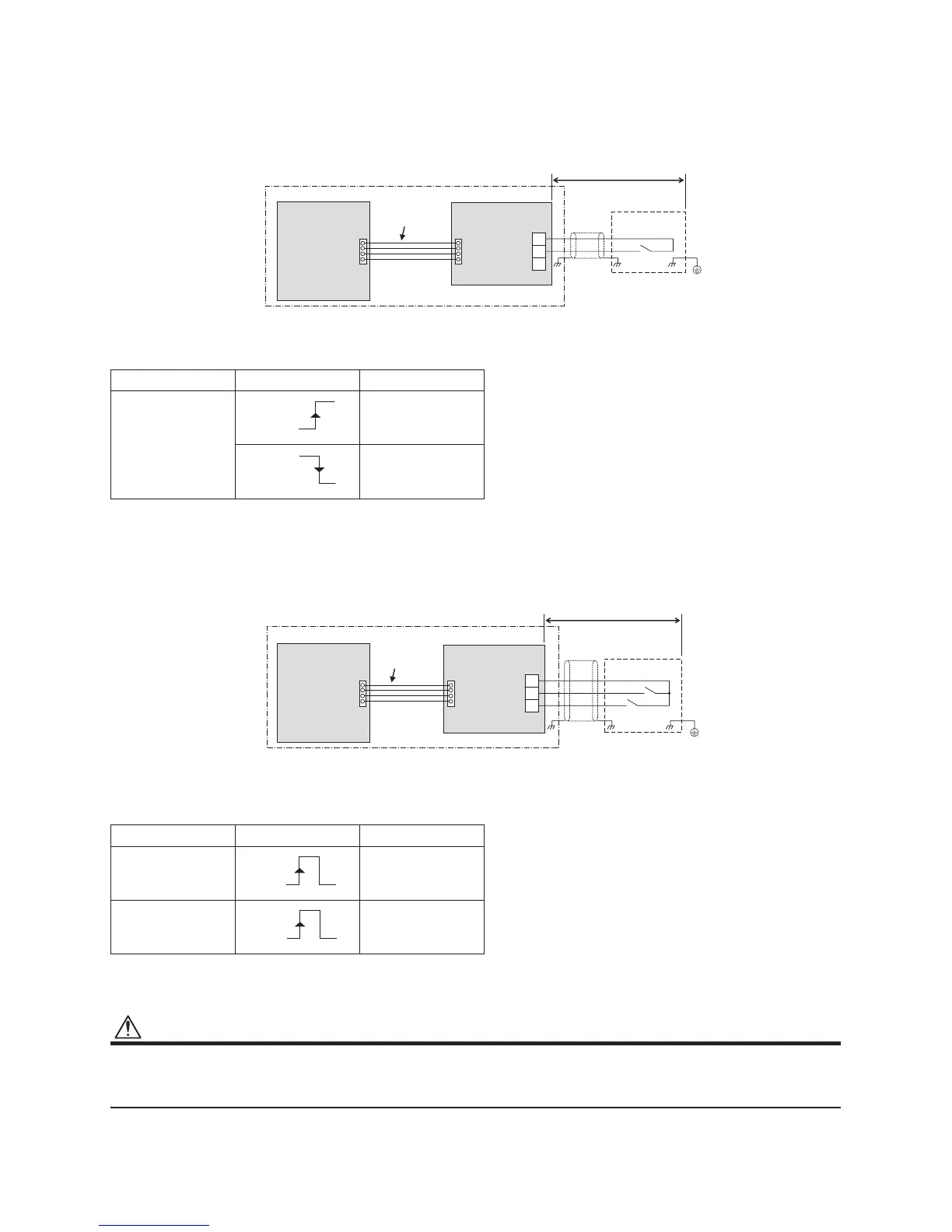
SW1: Snowfall detection switch (snowfall sensor)
CN509 PJ17
TB1
SW1
COM
HEAT
COOL
Locally procured
Optional PCB
Snowfall sensor
Header outdoor unit
Connection
cable
Outdoor unit
interface PCB
Shield
wire
ON
OFF
ON
OFF
SW1: Operation input switch
SW2: Stop input switch
CN512 PJ17
TB1
SW1
SW2
COM
HEAT
COOL
Locally procured
Optional PCB
Header outdoor unit
Outdoor unit
interface PCB
Connection
cable
Shield
wire
ON
OFF
ON
OFF
 Loading...