279
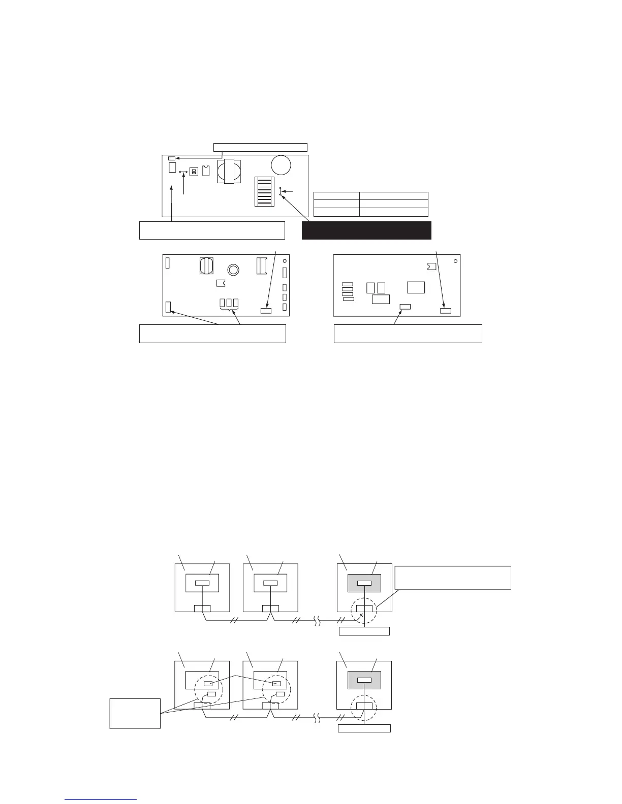
Procedure 2: Replacing P.C. Board
1 Replace the faulty P.C. board with a service P.C. board.
Be sure to replicate the old jumper setting (removal), switch setting (SW501), and connector short-circuit
setting (e.g. CN34) on the service P.C. board. (See the diagram at below.)
2 It is necessary to establish a one-to-one correspondence between the indoor unit being serviced
and the remote controller.
Turn on the indoor unit using one of the methods described below according to the system configuration.
(1) Single (stand-alone) operation
Turn on the indoor unit and proceed to Procedure 3.
(2) Group operation
A) If it is possible to selectively turn on the indoor unit being serviced
Turn on the indoor unit being serviced and proceed to Procedure 3.
B) If it is not possible to selectively turn on the indoor unit being serviced (Case 1)
a) Temporarily disconnect the group control wiring from terminals A and B of the indoor unit being serviced.
b) Connect the remote controller wiring to the terminals, turn on the indoor unit, and proceed to Procedure 3.
* If this method cannot be used, proceed to the alternative method described below (Case 2).
C) If it is not possible to selectively turn on the indoor unit being serviced (Case 2)
a) Remove the CN41 connectors of all other indoor units in the same group.
b) Turn on the indoor unit and proceed to Procedure 3.
* Be sure to restore the temporarily removed group control wiring and CN41 connectors to their initial states after
Procedure 3 has been completed.
CN34
(red)
SW501
J01
J02
(MCC-1403)(MCC-1402)
(MCC-1570)
CN030
CN41
CN34
CN041
Connector for drain pump (CN504)
AP009~AP030
AP036~AP056
Cut
Present (factory default)
J02
If a short-circuiting plug had been used on the
replaced P.C. board, reuse it on the service P.C. board.
The type and capacity of the indoor unit
are necessary for fan speed setting.
* Set the jumper wire J02 according to
the capacity class as shown below.
Be sure to set this jumper as required to make
the selection of a motor protection level possible.
From left: CN112, 111 and 110
If a short-circuiting plug had been used on the
replaced P.C. board, reuse it on the service P.C. board.
If a short-circuiting plug had been used on the replaced
P.C. board, reuse it on the service P.C. board.
A B
Indoor unit
P.C. board
A B
Indoor unit
Group control wiring
Group control wiring
P.C. board
Indoor unit
P.C. board
Indoor unit
P.C. board
A B
Indoor unit (one being serviced)
Service P.C. board
Remote controller
Indoor unit (one being serviced)
Service P.C. board
Remote controller
A B A B A B
Case 1
Case 2
CN
41
Remove group control wiring from terminals
A and B of indoor unit being serviced, and
connect remote controller wiring.
Remove CN41
connectors of all
other indoor units
in same group.
 Loading...