85
6
Applied Control and Functions
(including Circuit Configuration)
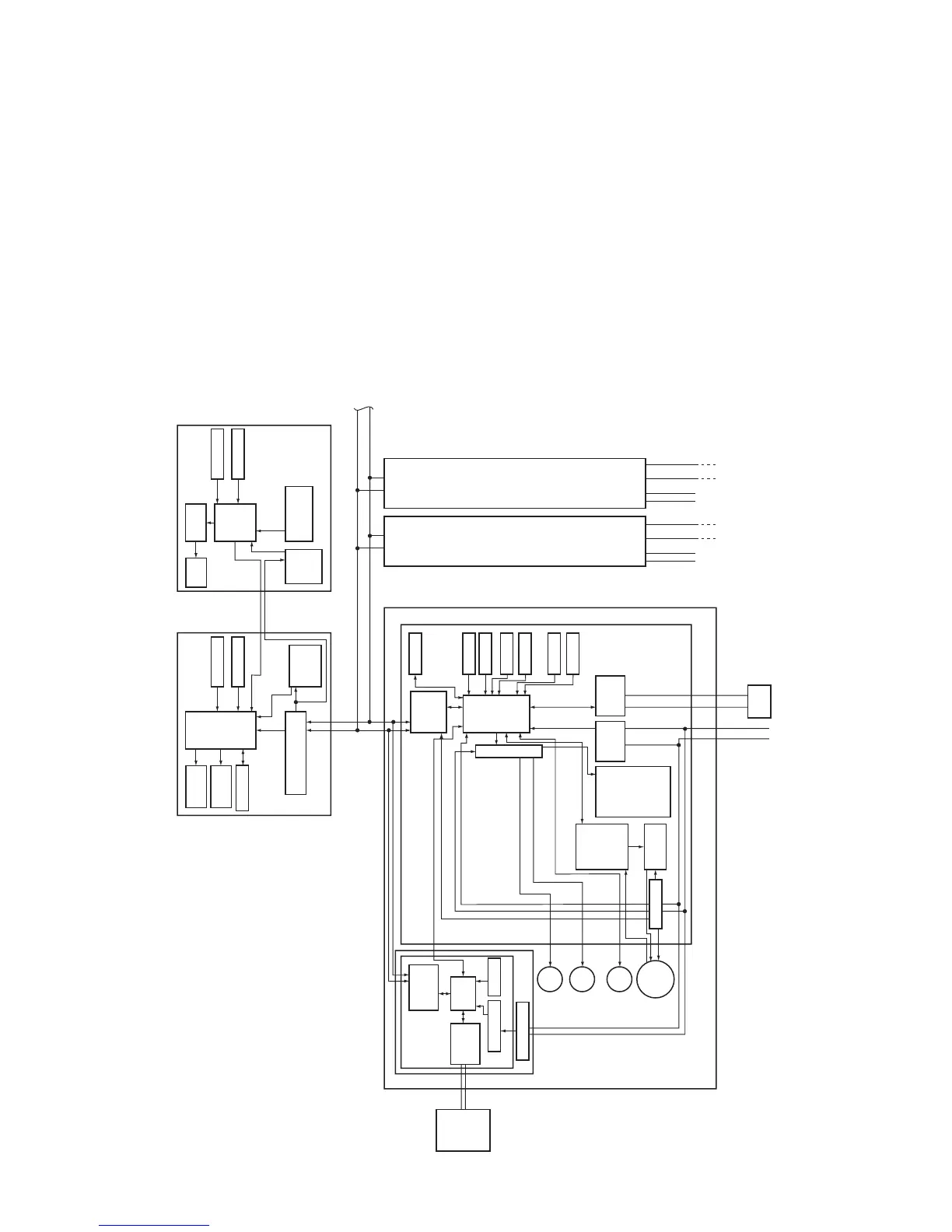
6-1. Indoor Controller Block Diagram
6-1-1. When Main (Sub) Remote Controller Connected
<New 4-way Air Discharge Cassette Type> (MMU-AP 2H)
Indoor control P.C. board (MCC-1570)
Network adaptor (optional)
Indoor unit
Main (sub) center remote controller (up to 2 units)
Schedule timer
(when in weekly timer mode)
Power
supply
circuit
Function setting
Key switch
EEPROM
MCU
Switch setting
Power supply circuit
Power supply circuit
Transformer
DC5V
DC5V
CN2
*3
CN1
DC5V
MCU
EEPROM
HA
Remote controller
communication circuit
Display
LCD
MCU
Rechargeable
battery
MCU
LCD
driver
MCU
External output
DC 280V
DC5V
DC12V
DC20V
PMV
X
Y
A B A B A B
×4
Indoor/outdoor communication
U1
U1 U2
U2
R S
U1
U2
R S
U1
U2
Display
LED
Display
LCD
Function setting
Key switch
Power
supply
circuit
Central
control
remote
controller
(optional)
Network
adaptor P.C.
board
(MCC-1401)
Remote controller
communication
circuit
Remote
controller
communication
circuit
AI-NET
communication
circuit
Louver
motor
Drain
pump
Indoor
fan
motor
Fan motor
control circuit
In operation
Alarm
Getting ready
Thermostat ON
COOL
HEAT
FAN
Driver
TA sensor
TCI sensor
TC2 sensor
TCJ sensor
Float input
AC
synchronization
signal input circuit
BUS
communication
circuit
Outdoor
unit
Outdoor
unit
Outdoor
unit
Power source
1Ø 220-240V, 50Hz
1Ø 220V, 60Hz
Power
source
Power
source
Sameas left
*2
Sameas left
*2
Up to 8 units can be
connected. *1
*1 Only up to 7 units if a
network adaptor is
installed with 2 main
(sub) remote controllers
connected.
*2 The network adaptor can
only be installed in one
unit.
*3 A weekly timer cannot
be connected to a sub
remote controller.
#2 #3
#1
(In case of
AI-NETWORK)
L N
 Loading...