41
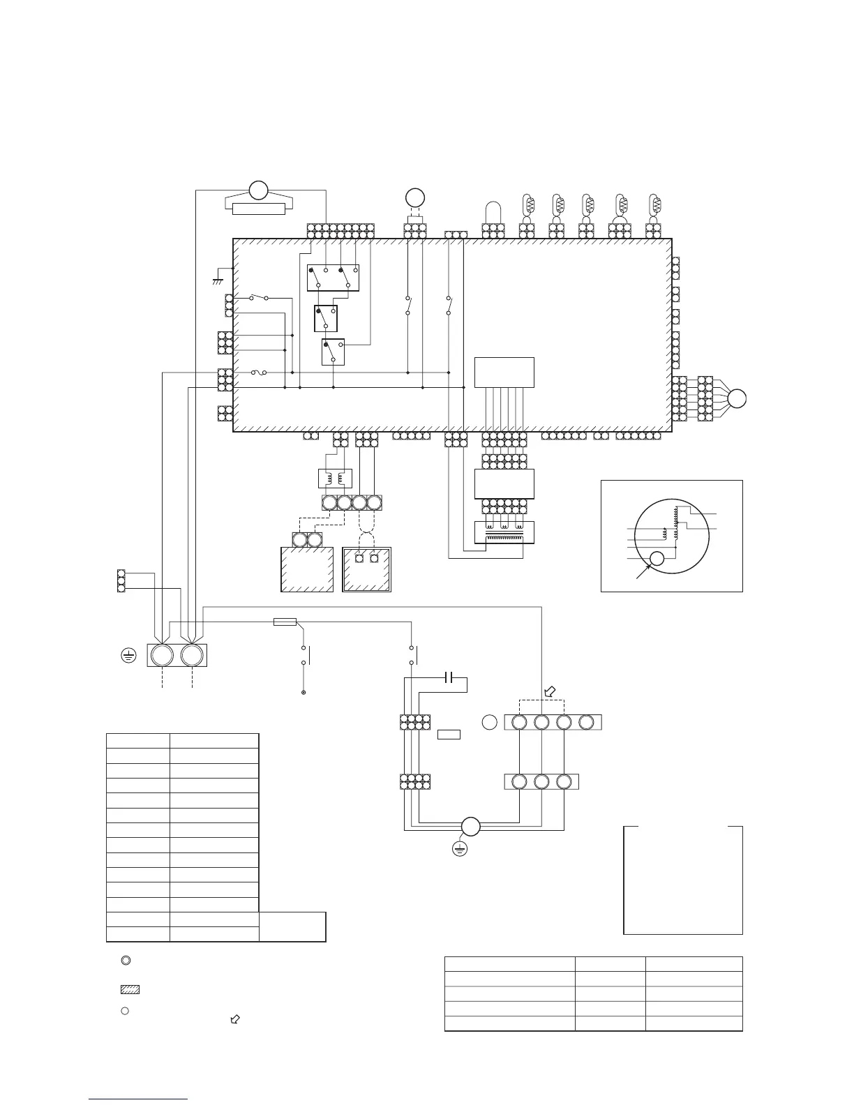
1-2-16. Fresh Air Intake Indoor Unit for S-MMS
Model: MMD-AP0481HFE
BA
U2U1
U2U1
2
3
1
2
1
2
1
2
3
4
5
1
654321
213121212131
212 312121212 3131
654321654321
654321
654321
654321
654321
654321
54321 321
321
32121
3121
21 21
Option
(Option)
8 7 REDWHI
TF
Fan driveT10
ORNBLU
TC2TCJ TA TC1
CN103
(GRN)
CN100
(BRW)
CN101
(BLK)
CN102
(RED)
CN104
(YEL)
CN030
(RED)
FS
Fan motor inside wiring diagram
Motor over heating protection switch
RED
WHI
GRY
BLK
BLU
ORN
LM
CN033
(GRN)
31
31
Fan
CN083
(WHI)
DP
CN068
(BLU)
13579
7
Surge absorber
ULLMHRY007
P301
RY006
RY005
RY002 RY001
CN304 (GRY)
CN309 (YEL)
CN067 (BLK)
CN066 (WHI)
Fuse
T5.0A, 250V ~
RED ACIN
WHI
RY004
BLK
1
3
1
3
1
11
22
3
1
3
1
3
1
3
5
4
3
2
6
5
4
3
2
6
2
1
3
4
5
2
1
3
4
1 1 6 6
5
PMV
43F1
DP
CN080
(GRN)
CN073
(RED)
CN070
(WHI)
CN081
(BLK)
CN082
(BLU)
CN060
(WHI)
CN032
(WHI)
CN061
(YEL)
CN075
(WHI)
CN074
(WHI)
CN050
(WHI)
CN041
(BLU)
CN040
(BLU)
BLU BLK BLKBLU
EMG
Line filter
Remote
controller
board
Outdoor unit
F1
YEL
RED
Indoor unit
earth screw
Power supply
220 – 240V ~ 50Hz
220V ~ 60Hz
Closed-end
connector
4P (WHI)
RC
4P (WHI)
Connector
Remote controller
RED
RED
RED WHI
WHI
WHI
WHI
RED
GRY
WHI
RED
GRY
WHI
RED
GRY
WHI
RED
GRY
REDT10A, 250V ~
CN044
(BRW)
Power
supply circuit
Sub P.C. board
MCC-1520
CN02
(YEL)
CN01
(WHI)
TR1
Control P.C. Board
for Indoor Unit
MCC-1403
BA
BLK
Parts name
Fan Motor
Running Capacitor
Transformer
Intake air temp. sensor
Blow temp. sensor
Temp. sensor
Fan motor control relay
Drain control relay
Pulse Motor Valve
Fuse for fan motor
Fan motor control relay
Drin Pump motor
Float Swotch
Symbol
FM
RC
TR1
TA
TF
TC1, TC2, TCJ
RY005 ~ 007
RY002
PMV
F1
43F1
DP
FS
Terminal block No.
F1 (Low static pressure tap)
F2 (Intermediate static pressure tap)
F3 (High static pressure tap)
F4
Fan motor wiring
Blue (50/60Hz)
Orange (50/60Hz)
Bkack (50/60Hz)
—
Note
At shipment from factory
—
RED : RED
WHI : WHITE
YEL : YELLOW
BLU : BLUE
BLK : BLACK
GRY : GRAY
PNK : PINK
ORN : ORANGE
BRW : BROWN
G & Y : GREEN & YELLOW
1. indicates the terminal block.
Latter at inside indicates the terminal number.
2. A dotted line and broken line indicate the wiring at site.
3. indicates the control P.C. board.
4. When installing the drain pump connect the froat switch connector to CN030 connector.
5.
A position is connected to terminal block when change to static pressure.
Exchange the lead wire of arrow ( ) pisition after the terminal number as figure and
lead wire’s color of fan motor.
ORNBLU BLK
A
S(N)R(L)
5
43F1
3
6
43F1
4
4321
4321
4321
4321
FM
1 2 3
F1 F2 F3 F4
Fan 1
G & Y
49F
Sold separately
Color Identification
PNL
EXCT
Filter
 Loading...