 Loading...
Do you have a question about the Toshiba Tecra M10 and is the answer not in the manual?
| Tjunction | 100 °C |
|---|---|
| Processor cache | 2 MB |
| Processor cores | 2 |
| Processor model | T6570 |
| System bus rate | - GT/s |
| Processor family | Intel® Core™2 Duo |
| Processor socket | Socket 478 |
| Processor codename | Penryn |
| Processing Die size | 107 mm² |
| Processor frequency | 2.1 GHz |
| Processor cache type | L2 |
| Processor lithography | 45 nm |
| Processor manufacturer | Intel |
| Processor front side bus | - MHz |
| Processor operating modes | 32-bit, 64-bit |
| ECC supported by processor | No |
| Thermal Design Power (TDP) | 35 W |
| Number of Processing Die Transistors | 410 M |
| Motherboard chipset | Intel® GM45 Express |
| HDD speed | 5400 RPM |
| HDD interface | SATA |
| Optical drive type | DVD Super Multi |
| Card reader integrated | Yes |
| Total storage capacity | 320 GB |
| Compatible memory cards | Memory Stick (MS), MMC, MS PRO, SD, xD |
| Display diagonal | 14.1 \ |
| Display resolution | 1280 x 800 pixels |
| Native aspect ratio | 16:10 |
| Internal memory | 4 GB |
| Internal memory type | DDR2-SDRAM |
| Maximum internal memory | 8 GB |
| Discrete graphics card model | Intel® GMA 4500MHD |
| Maximum graphics card memory | - GB |
| Type | PC |
| Modem speed | 56 Kbit/s |
| Power supply type | AC |
| Power requirements | 100-240V, 50/60Hz |
| Compliance industry standards | IEEE 802.3, IEEE 802.3u, IEEE 802.3ab |
| DVD+R read speed | 8 x |
| DVD-RAM read speed | 5 x |
| DVD+R Double Layer read speed | 6 x |
| Bluetooth version | 2.1+EDR |
| Cabling technology | 10/100/1000Base-T(X) |
| Networking features | Gigabit Ethernet |
| Operating system installed | Windows Vista Business |
| Sustainability certificates | ENERGY STAR |
| Battery capacity | 5100 mAh |
| Number of battery cells | 6 |
| Charging port type | DC-in jack |
| USB 2.0 ports quantity | 4 |
| Parallel ports quantity | 0 |
| Product color | Silver |
| Storage temperature (T-T) | -20 - 65 °C |
| Operating temperature (T-T) | 5 - 35 °C |
| Storage relative humidity (H-H) | 10 - 90 % |
| Operating relative humidity (H-H) | 20 - 80 % |
| AC adapter power | 75 W |
| AC adapter output current | 5 A |
| AC adapter output voltage | 15 V |
| Pointing device | Touchpad |
| Processor ARK ID | 42841 |
| Depth | 245 mm |
|---|---|
| Width | 336.8 mm |
| Weight | 2440 g |
| Height (rear) | 38.4 mm |
| Height (front) | 36.4 mm |
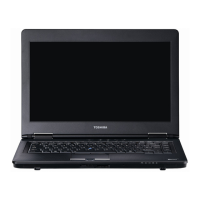
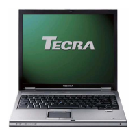
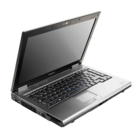
Details the various hardware components and features of the TECRA M10 laptop.
Illustrates the internal architecture and component connections of the system unit.
Covers LCD module and FL inverter board specifications for the TFT color display.
Explains the functions of the power supply and its output ratings.
Introduces how to determine Field Replaceable Units (FRUs) causing computer malfunctions.
Provides a guide for determining troubleshooting procedures based on system symptoms.
Describes procedures to check if the power supply is functioning properly.
Details how to determine if the system board is malfunctioning or not.
Provides procedures to check if the fingerprint sensor works correctly or not.
Explains how to use Diagnostic Test programs to test hardware modules.
Guides on how to start and run the repair test programs and their subtests.
Details how to execute the initial configuration program for hardware information.
Describes how to execute the System Test and its subtests like ROM checksum and Fan ON/OFF.
Guides on executing the Hard Disk Test and its subtests like Partition Check and Format Check.
Describes how to test unique functions of the model, like keyboard, touch pad, and LEDs.
Describes FRU removal/replacement procedures and provides a chart for FRU order.
Details the procedure for removing and installing the computer's battery pack.
Describes the procedure for removing and installing the 2.5-inch HDD.
Provides steps for removing and installing the computer's keyboard.
Provides procedures for replacing the system board, including DMI information management.
Details procedures for replacing fluorescent lamps for different LCD modules.
Provides safety precautions for handling the LCD module during assembly/disassembly.
Shows front and back views of system boards with connectors and ICs labeled.
Lists pin assignments for various connectors on system boards.
Explains how to rewrite the system BIOS program when updating the BIOS.
