E6581913
22
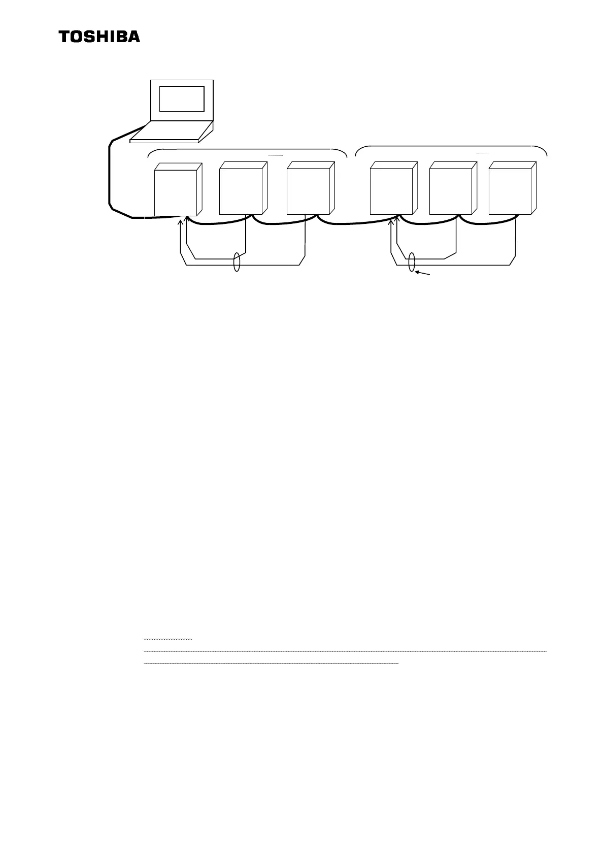
In broadcast communication, only the representative inverter in each block returns data to the
computer. However, you can make the representative inverter in each block report the occurrence
of a problem in the block. To do so, follow these steps.
Set the timer function so that, if a time-out occurs, the inverter will trip (Ex.: f803=3 (sec)), set
the output terminal selection parameter (FL) so that trip information will be output through the output
terminal (f132=10), and set the input terminal selection parameter (F) of the representative in-
verter in each block to “external input trip (emergency stop)” (f111=20, 21(Inversion)). Then,
connect the input terminal (F, CC) of the representative inverter to the FL terminal (FLA, FLC) of
each of the other inverters in the same block. In this setting, if an inverter trips, the representative
inverter will come to an emergency stop, and as a result it will report the occurrence of a problem in
its block to the computer. (If the representative inverter returns a lowercase letter in response to a
command from the computer, the computer will judge that a problem has arisen in an inverter.) To
examine details on the problem that has arisen, the computer accesses each individual inverter,
specifying its communication number. To make the computer issue a command to all inverters in
block 1 or block 2 shown in the figure above, specify “1*” or “2*”, respectively. In this system, in-
verter No. 10 will return data to the computer if a problem arises in block 1, or inverter No. 20 if a
problem arises in block 2. For overall broadcast communication, specify “**”, in which case the in-
verter with the communication number “00” will return data to the computer.
In this example, if you want the computer to maintain communication without bringing an represen-
tative inverter to an emergency stop, set its input terminal selection parameter to “disabled
(f111=0) but not to “external input trip (emergency stop).” This setting causes the computer to
check the setting of the input terminal information parameter (Communication No.=FE06, bit 0) of
the representative inverter, and as a result enables the computer to detect the occurrence of a
problem.
CAUTION:
Data from inverters will be deformed if inverters of the same number are connected on the network.
Never assign same single numbers to inverters on the network.
Host
computer
Inverter No. 10 Inverter No.11 Inverter No.19
Inverter No.20 Inverter No.21
Inverter No.29
*1: Error signal I/F
*1
Block 2
Block 1
Inverter
Inverter Inverter Inverter Inverter
Inverter
Phone: 800.894.0412 - Fax: 888.723.4773 - Web: www.clrwtr.com - Email: info@clrwtr.com
 Loading...