E6581913
4
2. Data transmission specifications
Items Specifications
Transmission scheme Half-duplex
Synchronization scheme Start-stop synchronization
Communication baud rate 9600/19200*/38400 bps (selectable using a parameter)
*1
Communication protocol Toshiba inverter protocol * / Modbus RTU protocol (selectable using a parameter)
*1
Character transmission <ASCII mode> JIS X 0201 8-bit (ASCII)
<Binary mode, Modbus RTU> Binary codes fixed to 8 bits
Stop bit length Received by inverter: 1 bit, Sent by inverter: 2 bits
*3
Error detecting scheme Parity
*2
: Even */Odd/Non parity (selectable using a parameter)
*1
,
checksum(Toshiba inverter protocol), CRC(Modbus RTU protocol)
Character transmission
format
11-bit characters
*1
(Stop bit=1, with parity)
Order of bit transmission Least significant bit sent first
Frame length Variable
*1: Changes to setting do not take effect until the inverter is turned back on or reset.
*2: JIS-X-0201 (ANSI)-compliant 8-bit codes are used for all messages transmitted in ASCII mode
and vertical (even) parity bits specified by JIS-X-5001 are added to them. These even parity bits
can be changed to odd parity bits by changing the parameter setting (a change to the parameter
setting does not take effect until the inverter has been reset.)
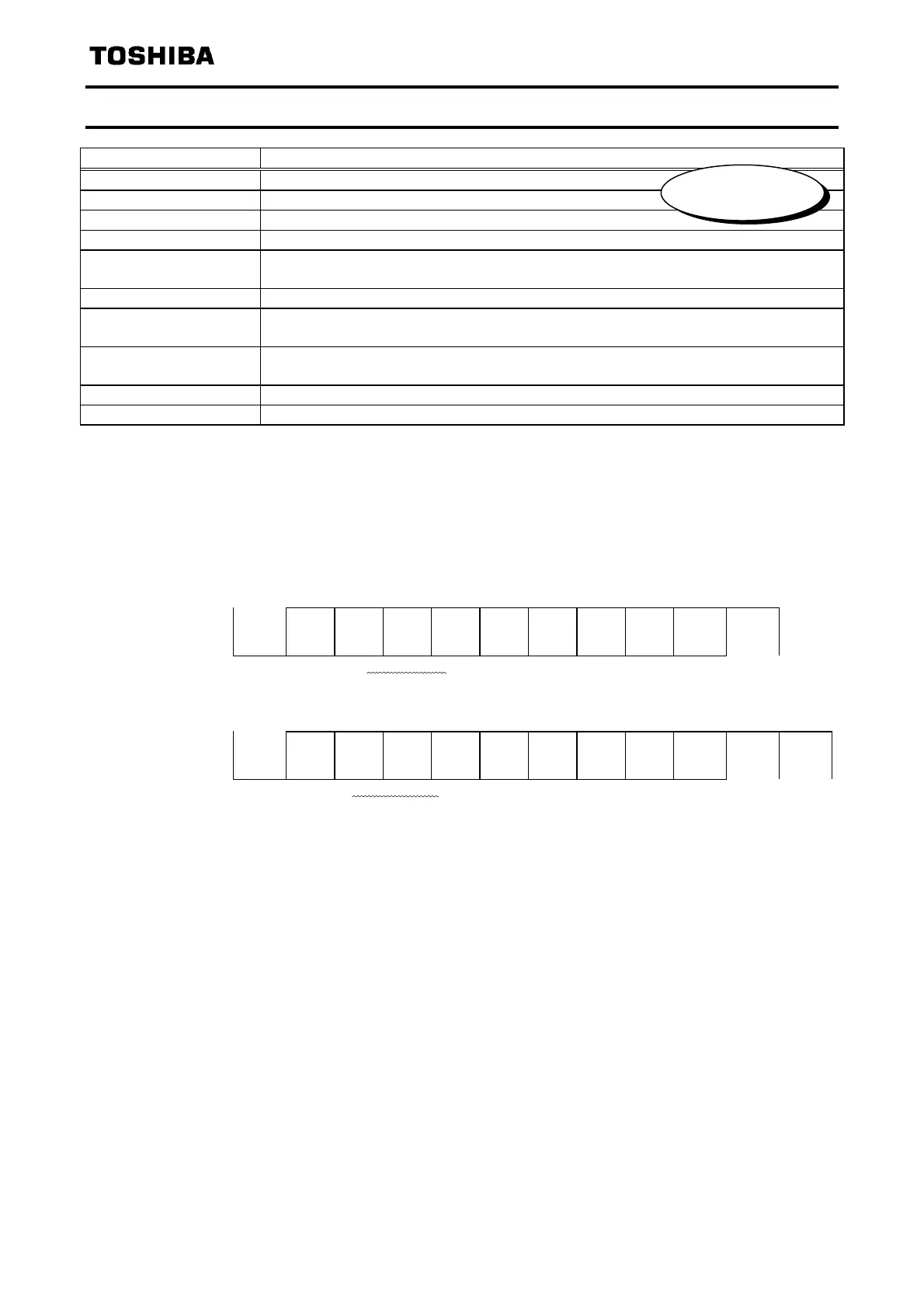
*3: The following is the character transmission format.
Characters received: 11 bits (1 start bit + 8 bits + 1 parity bit + 1 stop bit)
START
BIT
BIT0
BIT1
BIT2
BIT3
BIT4
BIT5
BIT6
BIT7
PARITY
BIT
STOP
BIT
The inverter receives one stop bit.
(The computer can be set so as to send 1, 1.5 or 2 stop bits.)
Characters sent: 12 bits (1 start bit + 8 bits + 1 parity bit + 2 stop bits)
START
BIT
BIT0
BIT1
BIT2
BIT3
BIT4
BIT5
BIT6
BIT7
PARITY
BIT
STOP
BIT
STOP
BIT
The inverter sends two stop bits.
(The computer can be set so as to receive 1, 1.5 or 2 stop bits.)
*: Standard
default setting
Phone: 800.894.0412 - Fax: 888.723.4773 - Web: www.clrwtr.com - Email: info@clrwtr.com
 Loading...