E6581913
44
6.1. Speed proportional control
Proportional control of frequency can be performed in two ways: control by selecting frequency
points and control by adjusting the ratio to the maximum frequency. This section explains propor-
tional control of inverters by means of a master inverter (inter-drive communication), although the
VF-S15 series inverters are ready for proportional control by means of the “S” command even when
they are operated under the control of a computer (computer-linked communication) (in the latter
cases, read the master inverter as the computer).
Proportional control can also be performed in units of Hz using ordinary write commands (W and P
commands) (frequency point selection only). For proportional control in units of %, however, the S
command should be used.
* For proportional control by selecting frequency points, the gradient can be set variously according
to the way each inverter is used. For proportional control by controlling the ratio to the maximum
frequency, settings can be made easily without consideration of the rate at which the frequency is
increased or decreased to the target frequency.
Data sent by the master inverter to slave inverters in inter-drive communication mode (frequency
command value)
FHsideMaster
fcsideMaster
(%)fc
10000×
=
(1=0.01%)
* Fractions under 1 (0.01%) are omitted. Therefore, an error of 0.01% is introduced at the maxi-
mum.
Conversion of the frequency command received by a slave inverter (when the “frequency point
selection” option is not selected)
The value obtained by the following conversion calculation is written in RAM as a frequency com-
mand value.
10000
FHsideSlave(%)datareceiveSlave
)Hz(fc
(1=0.01Hz)
* Fractions under 1 (0.01Hz) are omitted. Therefore, an error of 0.01Hz is introduced at the maxi-
mum.
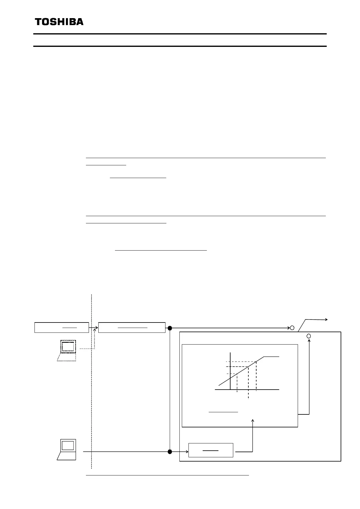
[Diagram of speed proportional control]
Slave command
Point conversion
fc
fcfc
1 oint-Point 1)+P
Point1Point2
2 Point
command= Sl a ve commandMaster(
intPo
1
FH Slave
10000
data receive Sl a ve
=HzData )(01000
FHMaster
Master
data= se ndMaster
fc
00010
FH Slave
Data=
fc
Setting 2
fc
(f814)
Point2
(f813)
Point1
(f811)
Master command
Setting 1
fc
(f812)
(Hz)
Hz
(%)
%
Operation performed by the
master (or use of S command)
<Outside> ← →<Inverter's internal computation>
Operation performed by the slave
%
%
Hz
Point selection (f810)
Fc
(Hz)
Points not selected
Points selected
* fc=frequency reference, FH=maximum frequency
Hz
If the “Frequency point selection” function is disabled (f810=0)
Phone: 800.894.0412 - Fax: 888.723.4773 - Web: www.clrwtr.com - Email: info@clrwtr.com
 Loading...