E6581913
75E
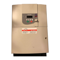
Appendix 5 Connecting for RS485 communication
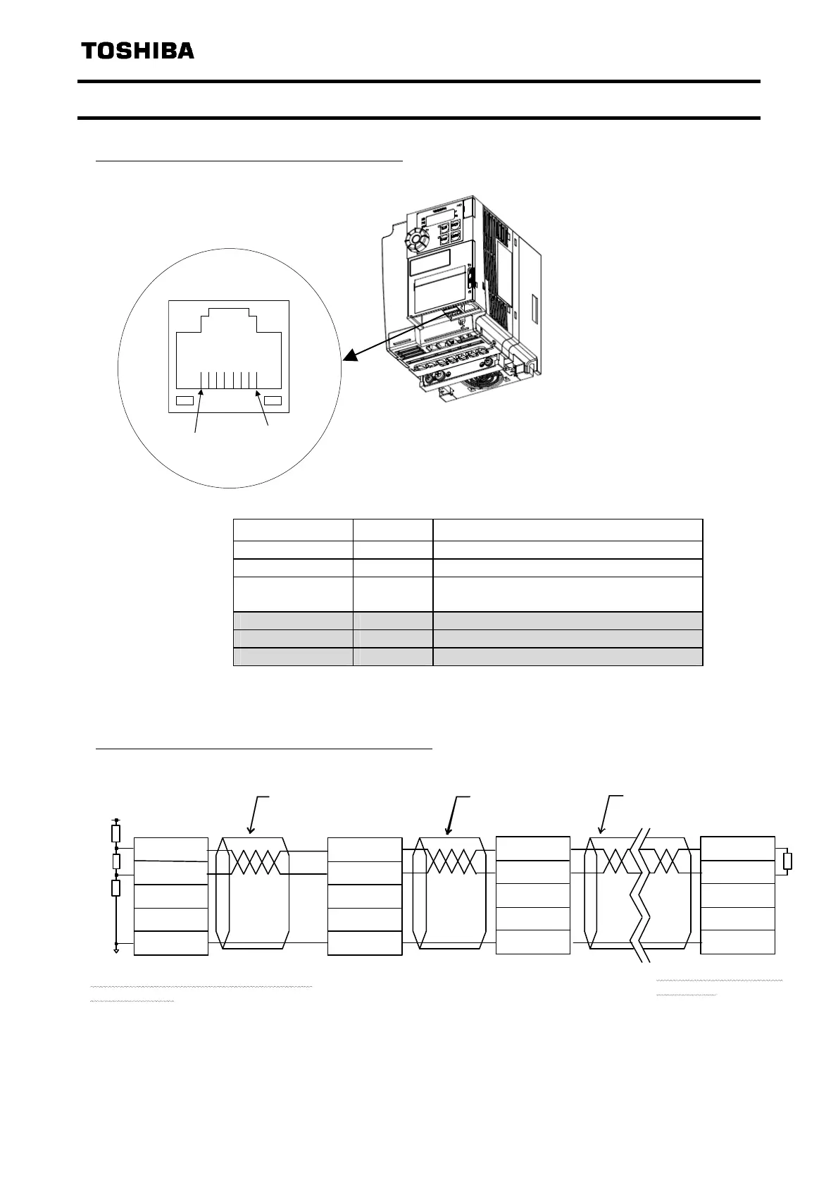
Connector diagram for two-wire RS485 communication
Pin assignment for two-wire RS485 communication example
* Never use pin-7 (P24).
Master
RXD+/TXD+
RXD-/TXD-
SG
CN1
510
120
Pin-4
Pin-5
Pin-8
(Pin-3)
Straight Straight
Straight
Slave
RXD+/ TXD+
RXD-/ TXD-
SG
Slave
RXD+/TX D+
RXD-/TX D-
SG
Slave
RXD+/TXD+
RXD-/TXD-
SG
P5
510
120
Terminati on resistor / Bias resis ters
120,510Ω-1/2W
Termination resistor
120Ω-1/2W
Signal name Pin number Description
RXD+/TXD+ 4 Same phase reception data (positive line)
RXD-/TXD- 5 Anti-phase reception data (negative line)
SG 8
(3)
Ground line of signal data
--- 6 --- (Do not connect the cable.)
--- 1,2 --- (Do not connect the cable.)
P24 7 24V (Do not connect the cable.)
1pin
8pin
Phone: 800.894.0412 - Fax: 888.723.4773 - Web: www.clrwtr.com - Email: info@clrwtr.com
 Loading...