EM-16
ENGINE MECHANICAL - Engine Tune-up
. . (
' l .
Z'\~
ENGINE TUNE-UP ·
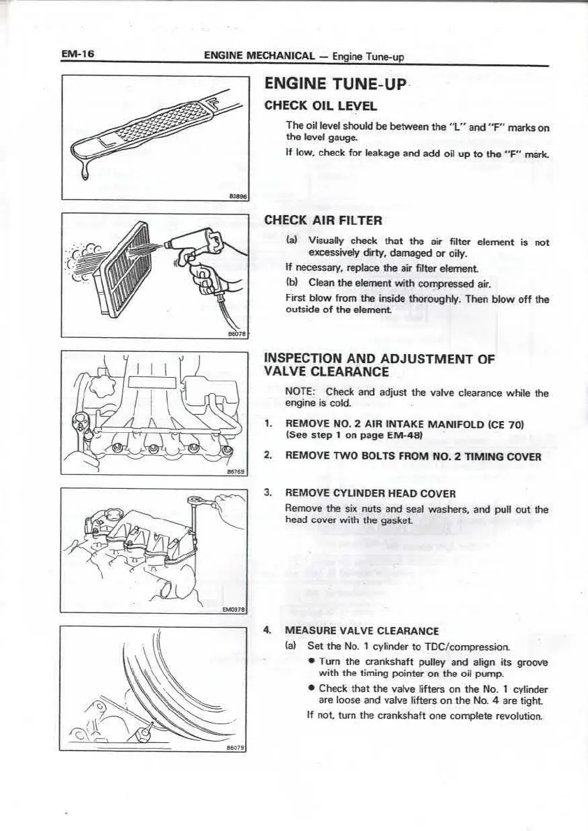
CHECK OIL LEVEL
The oil level should be between the " L" and " F" marks on
the level gauge.
If low, check for leakage and add oil up to the "F" mark.
CHECK AIR FILTER
!al Visually check that the air fit ter element is not
excessively dirty, damaged or oily.
tf necessary, replace the air fil ter element
(bl Clean the element with compressed air.
First blow from the inside thoroughly . Then blow off the
outside of the element
INSPECTION AND ADJUSTMENT OF
VALVE CLEARANCE
NOTE: Check and adjust the valve clearance white the
engine is cold.
1. REMOVE NO. 2 A IR INTAKE MANIF OLD ICE 70)
(See step 1 on page EM- 48 )
2. REM OVE TWO BOLTS FROM NO. 2 TIMING COVER
3. REMOV E CYLIND ER HEAD COV ER
Remove the six nuts and seal washers. and pull out the
head cover with the gasket
4. MEAS URE VALVE CLEARANCE
(al Set the No. 1 cylinder to TDC/ compression
• Tum the crankshaft pulley and align its groove
wit h the t iming pointer on the oil pump .
• Check that the valve lifters on the No. 1 cylinder
are loose and valve Utters on the No. 4 are tight
If not tum the crankshaft one complete revolut ion.
ENGINE MECHANICAL - Engine Tune-up
EM-'17
,.. Front
EX
IN IN
,.. Front
EX
o,am
11m
IN IN
Intake side:
New shim t hick.ness
= T + [A - 0.25 mm
(0.00 98 in.I]
Ex haust sid e:
New shim t hick ness
= T + [A - 0.30 mm
(0.01 18 in.)]
Oid 1H
(b) Measure the clearance of half of the valves.
• Measure only th ose valves indicated in th e f igure.
• Record the measurements w hich are out of
specification . They wiU be used later to determine
the required replacement shims,
Valv e clearanc e (Cold ):
Inta ke 0 .20 - 0.30 mm (0.008 - 0.012 in .I
Ex haust 0 .25 - 0.35 mm (0 .010 - 0.014 in.I
(cl Tum the crankshaft pulley one revolution and
measure the other valves.
• Tum the crankshaft pulley one revolution and align
its groove and timing poi nter on the oil pump.
• Measure only the valves indicated by the arrows in
the figure.
5 , ADJ UST VALVE CLEARANCE
NOTE: Vnlve clearance is adjusted one cylinder at a time.
(o) Turn the cronkshaft pulley to position the intake
com1holt lobe 11f the cylinder upward.
(hi Po11tlon lhe notch of lhe lifter so that ii is accessible
w11h • , moll aerewdrtver.
(cl Pince the SST between the two cams and tum the
hondle 10 press down the valve Utters .
SST 09248 -64010
NOTE: Make sure the SST is installed so that it presses
evenly on both lifters.
(d) Using a small screwdriver and magnet remove the
shims.
(el Determine the replacement shim size by using the
follow ing Formula and Charts .
• Using a micrometer. measure the thickness of the
shim that was removed.
• Calculate the thickness of a new shim so that the
valve clearance comes within the specified value.
T . . . . .. Thickness of shim used
A . , ... . Valve clearance measured
• Select a shim with a thickness as close as possible
to the calculat ed value.
NOTE: Shims are available in 25 sizes. in increments of
0.050 mm (0.0020 in.I. from 2.200 mm (0.0866 in.I to
3.400 mm (0.1339 in.l. Thickness is stamped o n the new
shims.
 Loading...