EM- 66
ENGINE ME CHA NICAL -·Cylinder Head
15 13 7 5 2 4 10 12 18
lM27l2
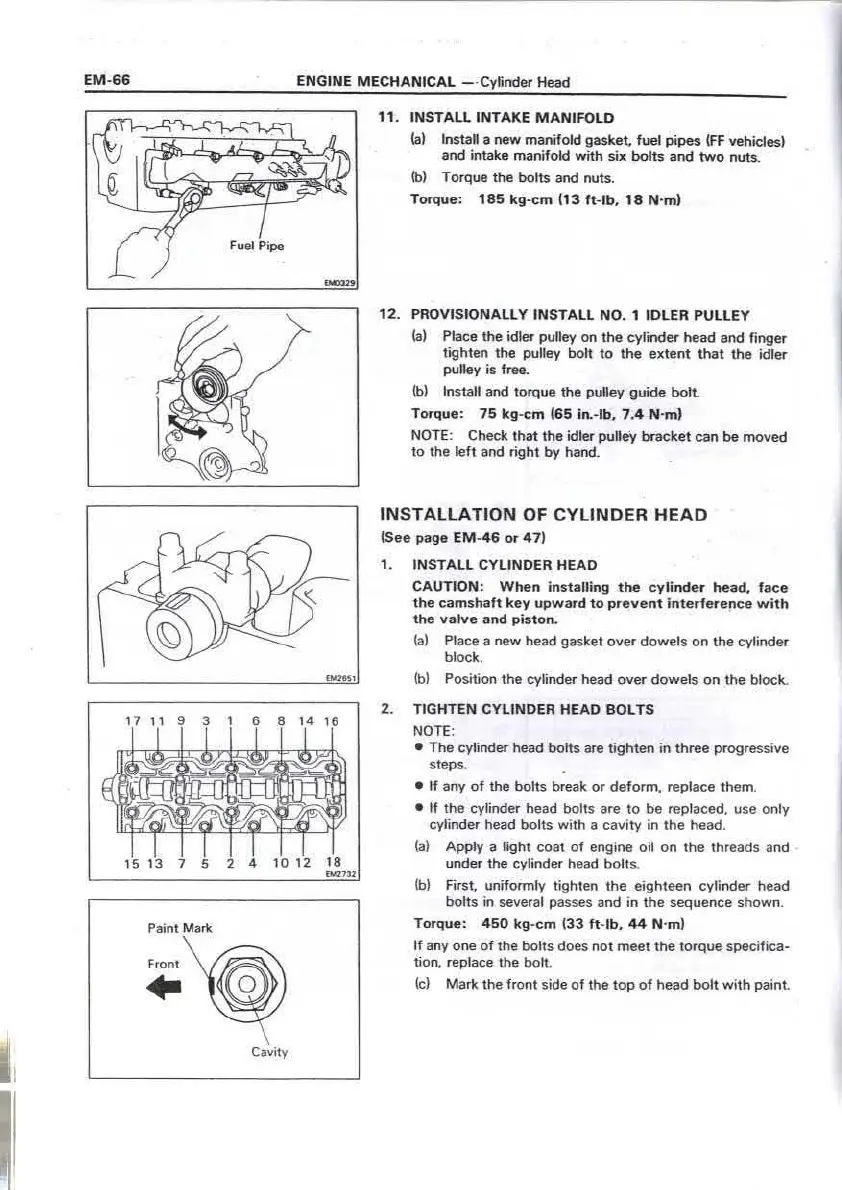
Paint Marl<
·~
Cavity
11 . INST AU INT A KE M ANIF OLD
(a) Install a new manifold gasket, fuel pipes (FF vehicles)
and intak e manifold with six bolts and two nuts .
(b) Torque the bolts and nuts.
Torque : 185 kg-cm (13 ft- lb, 1 8 N· m)
12. PROVI S ION ALLY INS T A LL NO. 1 IDLER PULLE Y
(a) Place the idler pulley on the cylinder head and finge r
tighten the pulley bolt to the extent that the idler
pulley is free.
(b) Install and torque the pulley guide boll
Torq ue: 75 kg-c m (65 in.-lb, 7.4 N·m)
NOTE: Check that the idler pulley bracket can be moved
to the left and right by hand.
INSTALLATION OF CYLINDER HEAD
(See page EM -4 6 or 47)
1. IN STAL L CYLI N DER HEA D
CAUT ION: W hen installing t he cyli nde r head, face
the camshaft key upward to preve nt interfe re nce wit h
the valve and pis1on.
(al Place a new head gasket over dowels on the cylinder
block.
(bl Position the cylinder head over dowels on the block.
2. T IGHTEN CY LINDER HEAD BOLTS
NOTE:
• The cylinder head bolts are tighten in three progressive
steps.
• If any of the bolts break or deform , replace them .
• If the cylinder head bolts are to be replaced, use only
cylinder head bolts with a cavity in the head .
(al Apply a light coat of engine oil on the threads and
under the cylinder head bolt s.
(bl First. uniformly tighten the eighteen cylinder head
bolts in several passes and in the sequence shown.
Torq ue: 4 50 k g-cm (33 ft- lb, 44 N ·m)
If any one of the bolts does not meet the torque specifica-
tion , replace the bolt.
(c) Mark the front side of the top of head bolt with paint .
ENGINE MECHANICAL Cyli nder Head
EM -6 7
£M2:142
(dl Tighten the eighteen head bolts 90° in the numerical
order shown.
(el Then tighten the bolts by an additional 90° .
(f) Check that the paint mark is now facing rea,ward.
3. IN STA LL CY LIN DER HEA D COV ER
(a) Place the head cover gasket on the head cover.
!bl Apply seal packing black (Part No. 08826-00080) to
four locations shown.
(cl Place the head cover on the cylinder head and install
the six seal washers and nut s. Torque the nuts.
Torque: 75 kg -cm (65 in.•lb, 7.4 N ·m)
4. IN STAL L N O. 3 TI M IN G BELT COV ER
5. IN STAL L CA M SHA FT TIMING PUL LEY
(a) Align the points marked during removal. and install
the timing belt on !he liming pulley .
(b) Match the key hole of the timing pulley with the key
on the camshaft .
(cl Using SST to hold the timing pulley , install and tor-
que the pulley bolt wi th the plate washer .
SST 09278 -5 4012
Torq ue: 900 kg -cm (65 ft- lb , 88 N ·m)
CA UTI ON: Avoid turn ing t he camsha f t or the valves
will hit against the pisto n. ·
 Loading...