EM-2 4 ENGINE MECHAN ICAL - Engine Tune-up
(b) Cut the maximum adjusting screw wire .
(cl Loosen the lock nut and adjust by turning the max-
imum speed adjusting screw.
CAUTION: Perform adjustment at low rpm , and then
recheck at maximum speed.
(di Securely tighten the lock nut and recheck the max"-
lmu m speed .
(e) Loci< the maximum speed adjusting screw with the
wire.
6 . CONNECT ACCELERATOR CABLE
(a) Connect the accelerator cable and adjust so there is
no slack in it
(bl Inspect to see that the adjusting lever is stopped by
the maximum speed adjusting screw when the
accelerator pedal is depressed an the way .
7. DISCONNECT TA CHOMETER
ENGINE MECHANICAL - Compression Check EM-25
,_ ..
_COMPRESSION CHECK
1.
2.
3.
4 .
5.
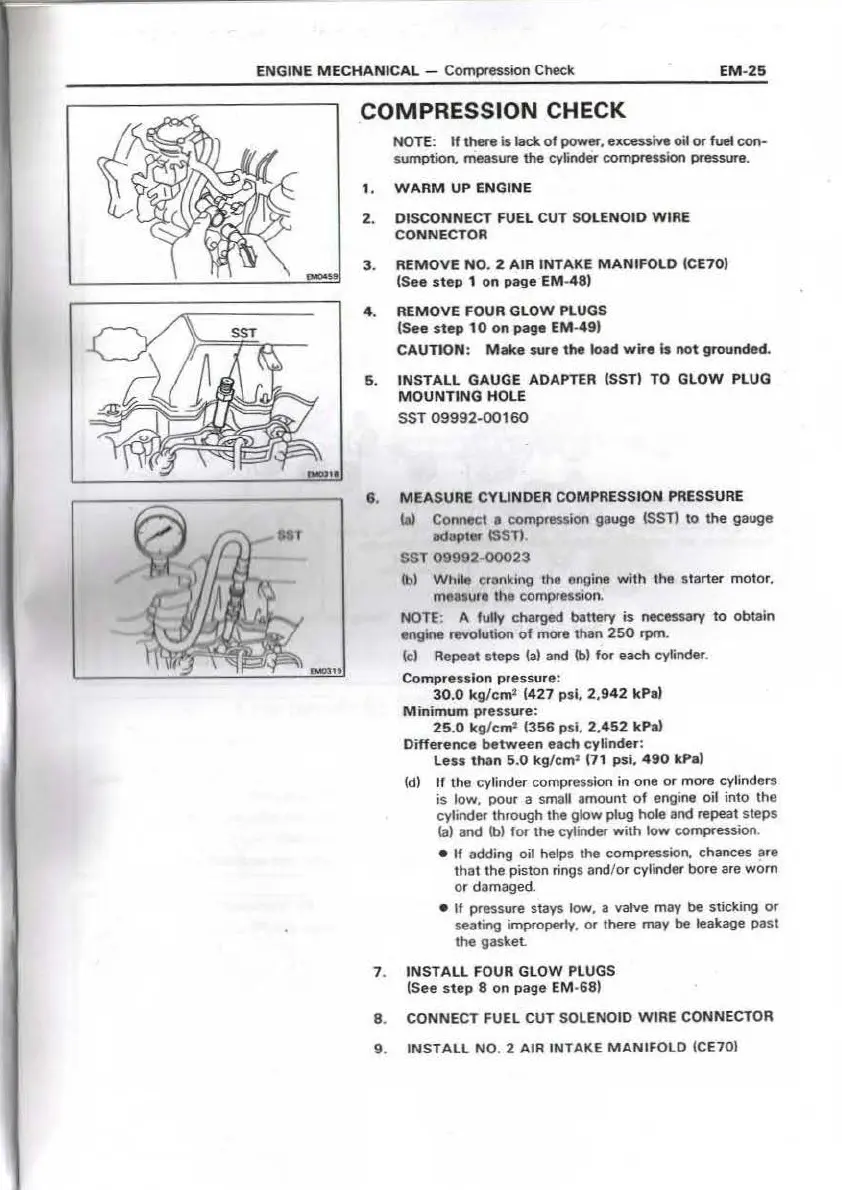
NOTE: If there is lack of power. e"=ive oil or fuel con-
sumption. measure the cyfinder compression pressure.
WARM UP ENGINE
DISCONNECT FUEL CUT SOLENOID WIRE
CONNECTOR
REMOVE NO. 2 AIR INTAKE MANIFOLD ICE70 )
(See step 1 on page EM-48)
REMOVE FOUR GLOW PLUGS
(See ste p 10 on page EM-49 )
CAUTION : Make sur e the load wire Is not ground ed.
INSTALL GAUGE ADAPTER (SST) TO GLOW PLUG
MOUNTING HOLE
SST 09992-00160
8. MEASURE CYLINDER COMPRESSION PRESSURE
la) Connect a compression gauge !SST) to the gauge
Ddopter ISSTI
SST 09992 00023
(b) While cranking the engine with the start er motor,
manure the compression.
NOTE: A fully charged battery is necessary to ob tain
engine nM>lution of more than 250 rpm.
(cl Repeat steps la) and lb) for each cylinder .
Compre-sslon pressure :
30 .0 kg/c m• (427 psi , 2,9 42 kPa)
Minimum pre ssure:
25 .0 kg/cm' (356 psi, 2 ,452 kP a)
Difference between each cyllnde-r :
Le ss tha n 5.0 k g/cm • (7 1 psi , 490 kPa)
{di If the cylinde r compression in one or more cylinders
is low, pour a small amount o f engine oil into the
cylinder through the glow plug hole and repeat steps
la) and lb) for the cylinder with low compression .
• If adding oil helps the compression, chances are
that the piston rings and/or cylinder bore are worn
or damage d-
• If pressure stays low , a valve may be sticking or
seating improperly, or there may be leakage past
the gasket_
7. INSTALL FOUR GLOW PLUGS
(See ste p 8 on page EM-68)
8 . CONNECT FUEL CUT SOLENOID WIRE CONNECTOR
9 . INSTALL NO. 2 AIR INTAKE MANI FOLD (CE70)
 Loading...