Chapter 3 Input and Outputs
16 CNT-SVX05B-EN
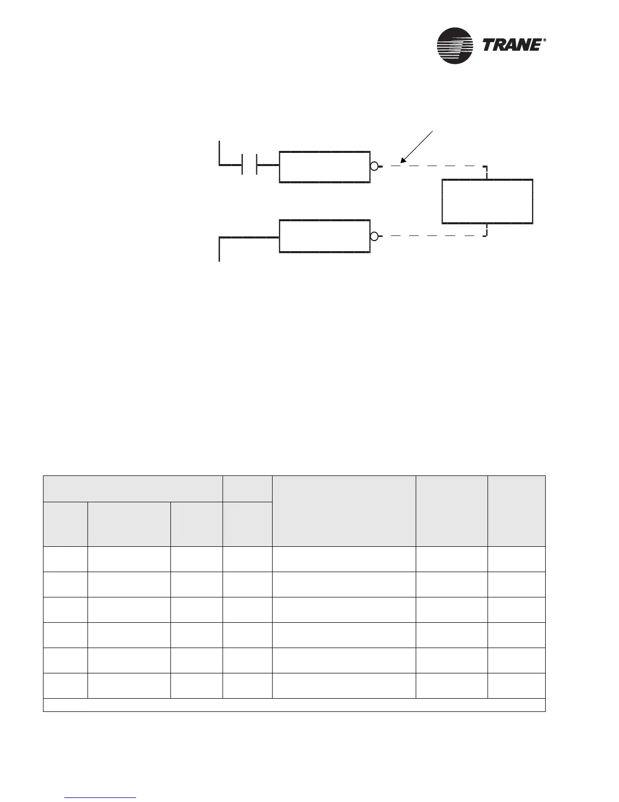
Figure 8. Binary output wiring schematic
Each binary output has a green status LED on the Tracer
AH540/541 con-
troller board (see Figure 1 on page 4). The LED is off when the relay con-
tacts are open. The LED is on when the relay contacts are closed.
When the binary output relay is Off (contact is open), a multimeter
should measure 0 Vac across the output terminals. When the binary out-
put relay is On (contacts are closed), a multimeter should measure 24 Vac
across the output terminals.
Analog outputs
The Tracer AH540/541 controller has five analog outputs that are
assigned to the specific functions shown in Table 4
Termination board
24 Vac
GND
GND
BO1
Supply fan
start/stop relay
Wiring external to the
termination board
Table 4. Analog output functions and locations
AH540 AH541
Function
Output range
default value
1
Maximum
output
rating
Output
label
Terminal label
Factory
terminal
label
Field
terminal
label
AO1 TB11/1 OUT
TB11/2 GND
J11 AO1 Supply fan speed 0 to 10 Vdc
ground
20 mA
AO2 TB12/1 OUT
TB12/2 GND
J12 AO2 Cool valve output or
two-pipe changeover
2 to 10 Vdc
ground
20 mA
AO3 TB13/1 OUT
TB13/2 GND
J13 AO3 Heat output (water, steam, or
electric heat sequencer)
2 to 10 Vdc
ground
20 mA
AO4 TB14/1 OUT
TB14/2 GND
J14 AO4 Face-and-bypass damper 2 to 10 Vdc
ground
20 mA
AO5 TB15/1 OUT
TB15/2 GND
J15 AO5 Outdoor air damper 2 to 10 Vdc
ground
20 mA
AO6 TB16/1
TB16/2
J16 AO6 Not used — —
1 Each analog output can be configured for 0–10 Vdc or 2–10 Vdc operation, and normally open or normally closed.

 Loading...


