CNT-SVX05B-EN 83
Chapter 6
Verifying operation and
communication
This chapter describes:
• Test button
• How to perform a manual output test
• Service Pin button
• Light-emitting diodes (LEDs)
• Diagnostic conditions
Test button
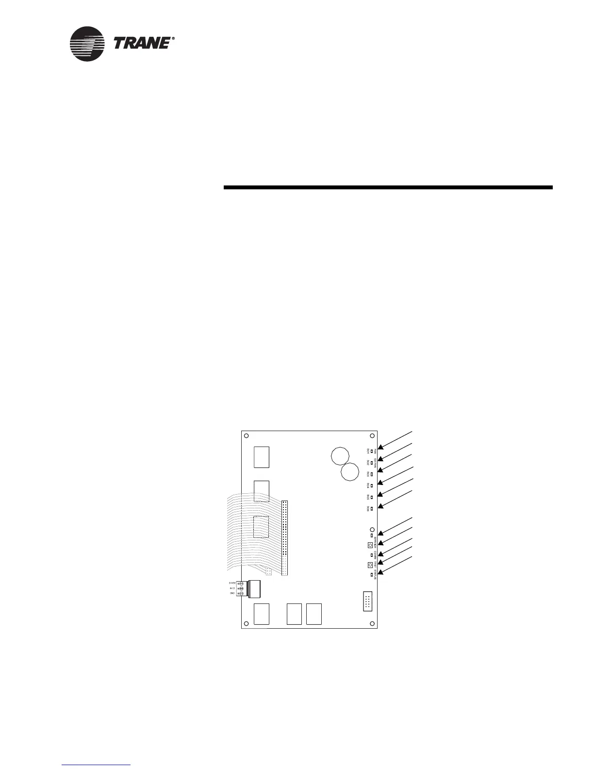
The Test button is located on the main controller board, as identified in
Figure 14. You can use it to perform the manual output test, which veri-
fies that the controller is operating properly. The manual output test is
described in the next section.
Figure 14. Locations of Test button, Service Pin button, and LEDs
Supply fan LED (green)
Exhaust fan LED (green)
Service Pin button
Comm LED (yellow)
Status LED (green)
Tes t b u tt o n
DX 1 or electric heat 4 LED (green)
DX 2 or electric heat 3 LED (green)
DX 4 or electric heat 1 LED (green)
Service LED (red)
DX 3 or electric heat 2 LED (green)

 Loading...


